
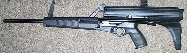
 The Calico uses a delayed roller block action, similar
in operation to that of the H&K G3, and CETME series of assault rifles.
These rifles fire a full powered cartridge, and are really more like automatic
battle rifles, than assault rifles. Applying this system to weapons firing
the much less powerful, and smaller 9mm pistol round makes for a very strong,
reliable, safe and accurate weapon.
The Calico uses a delayed roller block action, similar
in operation to that of the H&K G3, and CETME series of assault rifles.
These rifles fire a full powered cartridge, and are really more like automatic
battle rifles, than assault rifles. Applying this system to weapons firing
the much less powerful, and smaller 9mm pistol round makes for a very strong,
reliable, safe and accurate weapon.
The bolt unit consists of the bolt, which is mounted
on a bolt carrier containing the recoil springs. The bolt itself is
a three part assembly which is held together by it's own separate spring
and rod assembly. The forward portion of the bolt has a pair of rollers,
one mounted on each side. These rollers fit into recesses milled into the
sides of the upper receiver, thus locking the bolt in place. The rollers are
not stationary, however. They are mounted in such a way that they may retract
into the bolt. What holds them in place is a wedge in the second section
of the bolt. The second section of the bolt fits partially inside of the
forward section. While the two sections are nested together, a wedge in the
second section of the bolt fits between the rollers on the forward section,
keeping them apart, and extended. A guide rod fits through all three sections
of the bolt, and a spring rides on the guide rod. The rod and spring keep
the three sections of the bolt together.
When the weapon is fired, recoil forces act on the
bolt, but can not push the forward portion back, since it is locked in
place by the rollers. Thus the action stays closed. However, kinetic
energy can be transferred to the second section of the bolt, causing it
to move back. Because it is much heavier than the bullet, it takes longer
for the second section of the bolt to move back and release the rollers in
the forward section of the bolt, than it takes for the bullet to leave the
barrel, thus chamber pressures are down before the rollers are retracted.
Once the rollers are retracted, the entire bolt is unlocked and able to move
back. Inertia moves the bolt all the way back, and allows the empty cartridge
case to be ejected. The recoil springs force the bolt forward again, and
a new round is loaded. The whole thing is much simpler than it sounds, and
is quite a bit more reliable, and less fragile than the gas systems used
by most assault weapons.
Disassembly is pretty easy, as can be seen from below.
A single pin, just ahead of the ejector port, is pushed out, and the lower
unit is slid backward off of the upper unit. By pushing down through the
feed ramp, the bolt can then be pressed straight down out of the receiver.
This is as far as the weapon needs to be disassembled for cleaning and inspection.
Reassembly is done in reverse order, except that care should be taken to
make certain that the recoil springs in the bolt unit are slightly compressed
so that the unit can fit back into the receiver.
|
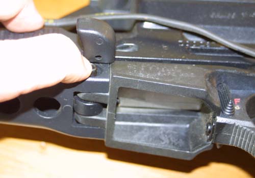
Location of the pin which holds the upper and
lower receiver sections together. Depressing it under the charging handle
causes the head to protrude from the other side of the lower receiver.
|
|
Getting a grip on the head of the pin, it can
be pulled all the way out. A detent prevents it from being lost. Once the
pin is removed, or extracted to the detent pin, the lower receiver may
be slid backwards off of the upper receiver. |
|
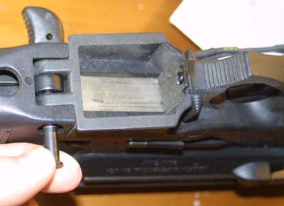
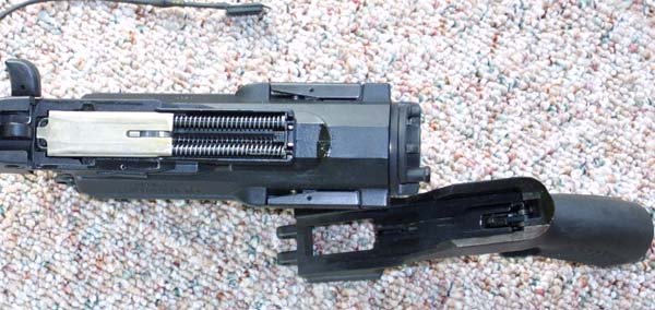
The Calico Pistol with the upper and lower
receivers separated. The bolt unit, with recoil springs, can be seen as
a bit of silver near the rear on the bottom of the upper unit. It is still
in place in the upper receiver. |
|
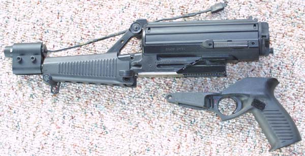
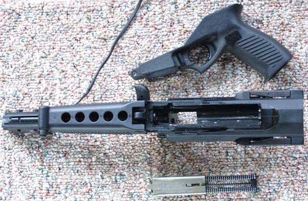
A view of the very simple lower unit standing
along side of the upper unit. The upper has been turned upside down to
show the placement of the bolt assembly. The bolt is separated from the
upper by first removing the magazine, and then pushing straight down on the
bolt through the feed opening. |
|
Upper lower, and bolt assembly. The Calico
is now completely stripped for cleaning. The two outside springs on the
bolt assembly are the recoil springs. The middle spring is the bolt
spring and guide rod. The three piece bolt itself can not be seen in this
view, because the assembly is turned upside down so that we are looking at
the bolt carrier. The catch visible on the underside of the bolt carrier
is where the trigger system connects with the striker. |
|
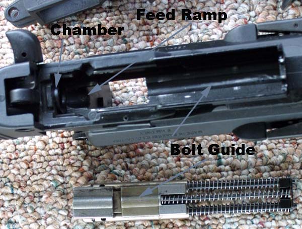
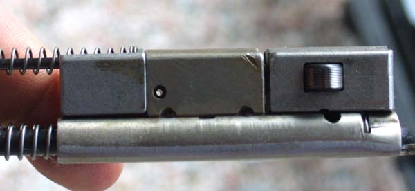
A closer look at the workings of the Calico.
The bolt assembly here is upside down relative to the receiver. The bolt
is at the bottom of the picture, and it can be seen that the forward and
second sections are separated, so that the rollers are retracted within
the forward section, and are not seen in this photo. The chamber and feed
ramp are visible here. It can also be seen that the top of the bolt has
a hump, which fits into a milled out guide in the receiver. This steadies
it as it reciprocates within the receiver. |

|
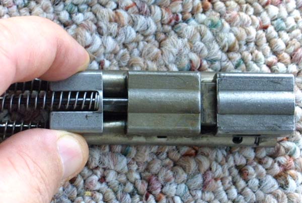
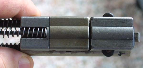
The bolt unit in this photograph is in battery
position with all three sections nested together. Note the rollers sticking
out of the sides of the bolt unit like ears. These fit into the recesses
milled into the upper receiver, holding the action closed until pressures
drop to safe levels. The rollers are forced out of the forward section
of the bolt by a wedge in the second section, which forces them apart when
the sections are nested together. |
|
The separate sections of the three part bolt
assembly are pulled apart here. Note that the rollers are retracted when
the bolt units come apart. The middle spring and guide rod keep them together
when in battery. |
|
The bolt assembly in battery with the rollers
extended. With the bolt in this position, the action is locked closed, and
can not be opened until transferred kinetic energy forces the second unit
back to unlock the rollers and allow them to be retracted within the forward
unit, as they are in the photo above. |
|
A side view of the three part bolt assembly
with the rollers extended. It sits on top of a bolt carrier with dual recoil
springs. |