The Antenna Farm
More like an antenna window box
| Introduction | My antenna farm | How they work | Polorization |
| Transmission line | Tuning and tuners | Attenuation | Antenna types |
| Stealth antennas | Indoor antennas |
People who live out in the country can have farms, if they like. Those who live in the city must content themselves with gardens, window boxes, or even indoor potted plants. The same holds true for amateur radio operators. Those who live in the country can have elaborate antenna farms with towers, large wire antennas strung everywhere, big beams, and the occasional vertical. Those who live in the city must make due with less. Because ham radio is a hobby, rather than a profession, overcoming these kinds of obstacles can be part of the fun, depending on your attitude. Who has a bigger thrill making that rare contact in Singapore or Australia, the guy who does it with a 30' beam on a 50' tower, or the guy who does it with a little wire antenna hidden in his attic? Who has more reason to be proud? So it is all a matter of perspective.
As always, when blazing new trails, it is best to start small. Experimenting with 2 meter is a good way to get your antenna design feet wet. For less than the cost of hiring movers after an eviction, the determined ham radio operator can purchase the tools to measure and run a really good array of stealth antennas. You may not be at as much of a disadvantage as you think.
How to overcome
this depends upon how obliging your neighbors, community, and/or landlord are
willing to be. It also depends upon the ingenuity (some would say sneakiness) of
the radio operator. I have heard of guys disguising antennas as flag poles,
hiding dipoles under the eaves of apartment buildings, making them look like
bird feeders or mobiles, or just hanging them out
a window, and hoping for the best. The usual objections are worries about
lightening strikes, concerns about RFI, and objections on the grounds that a
huge antenna farm is unsightly.
Generally, if you are a renter,
or live in a controlled community, you will have some pretty stringent
limitations on what you can use for an antenna. It is always easier for a
landlord, agent, or manager to say no than to say yes. Radio operators use what are
popularly called stealth antennas under these circumstances. There are basically
two versions of stealth. The first is the indoor antenna, and the second is the
disguised antenna. As a general rule, unless extreme compromises are required,
the disguised antenna outside, is better than an indoor antenna.
There are problems with indoor antennas, particularly at some frequencies. Transmitting through the walls of a structure can rob your signal of 10 - 15 db, depending upon the type of construction used, and the band being operated. Standard wood construction, without interfering wires, ductwork, or flashing, may absorb as little as 2 - 4 db at 800 MHz, and probably considerably less at lower frequencies. I have confirmed this, using handi talkies and my field strength meter. As a general rule, the higher the frequency, the greater the loss when penetrating materials. Disguised antennas tend to be easier for VHF and UHF, because the shorter wavelength allows for much shorter antennas. On the other hand, since most HF antennas are horizontally polarized (more on this below), they can sometimes be laid flat on a roof, or run around the eaves of a building, and will not show. Such solutions are far easier on a building with a flat roof, than on one where the roof slopes.
The problem I had was that I lived in a building where the owner actually did care about the place, and was aware of the property. I saw no other ham antennas on any of the other units, though I did see some satellite dishes, and even a tripod for a TV antenna. This gave me a few options. I could run my antennas indoors. I could hide my antennas. I could camouflage my antennas. I could put up good antennas, and hope for the best.
Obviously, the last choice was not a consideration. Putting up a huge antenna farm, would put me at risk of eviction, or at the very least irritate the building owner. I had considered the first choice, of putting my antennas indoors, and do have a full attic crawl space in which to do so; but there is a huge problem with this. Depending on the frequency, an indoor antenna can have a 10 – 15 DB loss over an outside antenna. This reduces the power by a factor of 8 – 30. So my Kenwood HF, at 125 watts, would be getting around 4 watts outside of my roofing. Unacceptable! Such attenuation is particularly hurtful on a multi band HF unit, due to the compromises already being made by trying to run and tune all bands into a single antenna. This is far less marked on the lower frequencies, and I have tested around and noticed almost no loss, when transmitting on HF through the walls and roof of my wood framed house. Before going any further though, it is best to take stock of the radios, and decide what antennas will actually be needed. I have no plans on getting anything fancy, like beams or any other kind of directional antennas.
As can be seen from the table below, my HF radios all use horizontal dipoles, while my VHF/UHF radios would use verticals. My 6 meter radio, which is a sort of a cross, has two antennas. My receiver also has multiple antennas, as it covers a wide range of frequencies. My radios are kept in the second floor of my townhouse, just beneath the attic crawl space. The advantage to this, is that it permits short feeder runs to my antennas. My attic measures 25' x 30' and is about 4.5' high at the peak. Generally, if you have an attic or a balcony you will have better options than the ham that has neither.
| Radio | Bands | Type | Location | Length | Feeder |
| Kenwood TK-860 | GMRS (460) | Ground plane small | Library/Shack | 6" x 12" | Coax |
| TS-711A | 2 meter (144) | Slim Jim (J-pole) | Library/Shack | 58" | Coax |
| TS-711A | 2 meter (144) | Dipole 2 | Attic ? | 38" | Coax |
| TS-50 | 6 meter (52) | Dipole 6 | Attic | Coax | |
| TS-50 | 6 meter (52) | Ground Plane 6 | Attic | Coax | |
| Console 5 | 11 meter | Ground plane CB | Attic | Coax | |
| PCR-100 | UHF | Discone small | Library | 5" | Coax |
| PCR-100 | UHF | Discone medium | Library | 11" | Coax |
| PCR-100 | VHF | Discone wire | Attic | 32" | Coax |
| PCR-100 | HF (SW) | Dipole fan | Attic | long wires | Coax |
| TS-440SAT | HF | Dipole Fan | Attic | long wires | Twin Lead |
Best materials are copper or aluminum, Learn from my mistakes and do not use steel. Though most people ordinarily think of steel as a conductor of electricity, it is not a good enough conductor to make it suitable for use as an antenna. Stainless steel is a good antenna material, but the sheet metal you get at the local hardware store is not stainless - it is galvanized. Incidentally, if anyone needs a few big sheets sheets of steel, let me know - just don't try using it for an antenna. It might be possible to copper plate steel sheets and use them, since radio energy is generated off of the skin of the antenna, but it was just getting to be too much trouble. I like to keep things simple.
The way my farm works is that I have two main antennas for SW/HF work, They are both multi element wire dipoles. One is for receiving on SW bands, and one is for transceiving on ham bands. The reason I need two different antennas is that the bands are different enough that antennas resonant on HF ham would not be resonant on SW. If I only were able to have one antenna, it would be resonant on ham bands, and I would tune it for SW.
The two multi wire dipoles are at approximately 90 degree angles to each other, so that they will not couple. Both slope across my attic ceiling. I did this to make the wire runs slightly longer, but also to remove the nulls at the end of the wires, by pointing them to the ground. The SW antenna is fed by a coax, and runs to the connector of my SW radio. The HF ham antenna is fed by ladder line, and runs to a tuner. The HF ham antenna is the only one of my antennas that uses ladder line.
Outside of these large antennas, I have single band horizontal dipoles for six meter and two meter. These are small enough that I do not have to angle them across the ceiling, and I also do not have to coil portions. They are fed by coax, and being single band antennas do not need a tuner once they are properly cut to resonant length. These are my smallest dipole antennas.
The rest of my antennas are verticals, either being ground plane or Slim Jim types. My smallest verticals are for 440 and GMRS. These are the highest frequency transmitters I have, and will thus experience the greatest loss when transmitting through a structure. A quarter wave radiator at these frequencies is about 6" long. I made a pair of them, one is a vertical dipole, and the other is a ground plane. i am considering making a Slim Jim. These antennas are so small, that they are in my shack, rather than needing to be placed up in the attic. This permits very small runs of coax, which is a good thin. These higher frequencies experience the greatest loss through transmission line.
Also in my shack, hanging on the wall, is my two meter Slim Jim. I may some day move this antenna to my attic, for the greater elevation; but for now it is unobtrusive in my shack. Two of my scanner antennas are in my shack. These are a pair of homebuilt discones, made from aluminum sheet. One is set up for low range UHF, and the other for high range. There is also a larger discone, made of stainless radials, which sits in my attic and is sized for VHF.
Currently, the attic contains three
vertical transmitting antennas. One is for six meter, and is a ground plane
design. it uses a quarter wave vertical element, and a number of wire radials.
The vertical element is 4.5 feet high. The radials are nine feet across. Across
from this is the CB antenna, which also has radials (out to sixteen feet), and
uses a 4.5 foot vertical with a base loading coil to make it resonant. While it
is possible that there might be some coupling between the radials of my
verticals and the sloping wires of my HF/ham antennas, it is not something I
worry about. As the radiators are at near 90% angles to each other, I foresee
little difficulty. The third vertical will be my two meter Slim Jim, once I find
the energy to move it.
How an antenna works
There are better places to learn antenna theory; but I felt obligated to put in my two cents worth. An antenna basically works by creating an electromagnetic field around two poles. When the two poles are opposite and equal, as in a classic dipole, you get a pattern that looks like a big donut, with the wire running through the hole of the donut. This pattern is broadside to the wire, and radiates nothing or nearly nothing off of the ends of the wires. These non radiating areas are known as nulls. Such an antenna creates a field which radiates equally in all directions (aside from the nulls), and is said to have no gain. A difficult concept to remember is that the antenna itself does not radiate, it only creates a magnetic field around itself. It is the magnetic field that actually radiates.
Gain is a misnomer. A high gain antenna does not increase power - it redirects and concentrates it. Still, this can be a significant advantage. Gain is increased by either adjusting the length of the antenna as a proportion of the wave length of the signal, or using various elements as reflectors and focusers of the generated signal.
Light is a form of electromagnetic
energy, like radio waves, and it can sometimes be helpful to picture the
familiar qualities of everyday light, when trying to understand the way radio
waves work. As frequencies change, the characteristics of electromagnetic
radiation change, so the light analogy is limited; but it is useful enough in
some cases. So lets think about a light bulb, the old fashioned filament kind,
and imagine that it is an antenna giving off radio waves instead of light waves.
In an old fashioned
light bulb, energy goes in, and is converted to heat and light (mostly heat in a
light bulb. It should be noted that light does not go into a light bulb
filament. It is electrical energy that goes in. The light bulb filament then
converts this electrical energy into light.
It also very inefficiently converts it into radio waves; but more on that
latter.
A typical human eye will respond to wavelengths from about 380 to 750 nm. In terms of frequency, this corresponds to a band in the vicinity of 790–400 terahertz. One wave length at these frequencies would be about the size of a bacteria. this would make the length of a quarter wave antenna less than that of the tiniest of smoke or dust particles, though still larger than the average virus. Still, what would you use as a feed line? We actually do see this resonance, when we see the rainbow pattern of an oil slick, or the similar pattern given off by diffraction patterns. Where an oil slick thins out enough to be resonant on certain frequencies fo light, we see these frequencies are the rainbow of the slick.
Making the light bulb filament longer, you would eventually get to a place where the resistance is too great, and the filament can not be made to give off current. It is difficult to give a good analogy to antenna lengths, because the wave length of light is so short. We are also unable to directly generate different wave lengths of light within the same filament.
LED and laser diode.
The problem with the light bulb analogy, is that it does not properly illustrate the idea of resonance. Light is resonant at lengths far below the length of a light bulb filament. For an idea of resonance, we must look to sound, another energy wave. Most of us are familiar, from our home music systems, with the idea of using multiple speaker elements to get full range reproduction of sound. Smaller speaker elements (tweeters) produce higher frequency sounds, while larger elements (woofers) are better at lower frequency sounds.
The various speaker elements are designed to be resonant at certain ideal frequencies, in the middle of the range of sounds they are configured to reproduce. Like any resonant system, they are compromises. Using multiple speaker elements is akin to using multiple antenna elements for a multi band dipole.
The two meter and six meter bands can be particularly challenging, especially the longer, 6 meter, because they are VHF, but are sometimes used for DX. For local contact, a vertical antennal is best; but for DX, you will want a horizontal dipole to catch the sky bounce. Fortunately, a 2 meter dipole is only three feet long, though a 6 meter dipole would be nine feet. Vertical antennas would be about the same, or perhaps a bit smaller. These bands should really have two antennas, one of each type of contact. This is not an extravagance; but is really needed on these bands - here's why. A vertical and a horizontal antenna have different polarity.
Radio waves, like any other member of
the electromagnetic spectrum, have a certain polarity, which can vary. You can
think of this as the way that they shake, either side to side, up and down, or
somewhere in between. The polarity is determined by the orientation of the
source, which in the case of radio waves would be the antenna. So if an antenna
is oriented straight up, like a car antenna, it is a vertical antenna, and the
radio waves it produces are vertically polarized. If it is parallel to the
ground, as is the case with most dipole antennas, it and the transmissions it
produces are said to be horizontally polarized. So what's the big deal?
Well, there are a couple of
consequences to antenna polarization. The first is the radiation pattern of the
antenna. Though this can be changed in more complicated multi element antennas,
a simple antenna with a single element will radiate in a pattern that appears to
be a big doughnut, with the antenna element running through the hole in the
middle. This pattern is the same, in horizontal and vertical antennas. What
should be noted though, is that the strongest signal will be radiating in a
circle, at a
right angle to the antenna element, while the weakest will be parallel to it. So
the direction in which both ends of the antenna point, will be somewhat deaf.
You can think of this as the filament in an old fashioned light bulb, with the
light being produced in the center section; but no real light being given off at
the ends.
Radio operators will tend to point
the deaf ends of their antennas towards areas that do not really matter - at
least to them. Thus, the standard CB or mobile antenna will be a vertical, so
that the deaf ends of the antenna will be pointing straight up, and straight
down, with the more active radiation pattern spreading out in every direction.
Such an antenna tends to look around to the horizon. This is ideal for local communication, and tends to be the standard for VHF and
UHF. For shortwave communications, at long distances on what ham operators call
the HF bands, antennas tend to be horizontal. The reason for this is that most of the
very long range communication is done by bouncing radio signals off of certain
electrically charged portions of the atmosphere. Thus, these antennas need to
radiate most strongly towards the sky. Unfortunately, this also means that much
of the signal will also be radiated directly into the ground. There are ways of
making an antenna more directional, through varying it's shape, or by the use of
multiple elements; but that is a whole other subject. Horizontal antennas are
often made of wire strung or run around the site. Vertical antennas tend to be
made of rigid tubing stuck straight up in the air.
There is one other factor to antenna
polarization. Antennas at sending and receiving points need to have the same
polarization. This can actually be a good thing, and helps the HF user filter
out local signals, and the UHF and VHF user filter out any possible static from
the sky. During receive, the function of the antenna is to gather radio
energy, for detection by the circuits of the radio. A voltage is produced in the
antenna, every time a radio wave crosses it. An antenna that has the same
polarization as a given radio signal will be offering a surface aligned with the
signal and thus have a broader contact with it. An antenna that is not of the
same polarization as a given radio signal will be turned into it and have less
surface area for absorption of energy. If this is hard to picture, think about a
boat being hit by a wave straight on. Now think about the same boat being hit by
a wave broadside. When the boat is hit straight on, the wave may have an effect;
but it is quite a bit less of an effect than of the boat is hit sideways. A
sideways hit transfers much more energy to the boat, rocking it and possibly
even tipping it over, which is why in storms sailors tend to hit the waves head
on, or head directly away from them, rather than letting the waves constantly
hit the boat sideways and tip it.
The difference in strength, between
an antenna that is of the same polarity as a signal, and one that it not can be
startling. It can be anything from 10 to 100 times the signal strength,
depending upon the original efficiency of the antenna. The ballpark number given
is 20db.
One of the most ignored elements of a radio station is the feeder line. This is the line between the radio and the antenna. Unless the feeder line is specially made to prevent propagation, any line connected to the radio will become the antenna. In some cases, this is desirable, as in a handi talkie. There are also those little back of the set antennas that people used to have for CB radios. These actually worked pretty well, because one of the dirty little secrets of radio is that most losses occur in the transmission line. Eliminate the transmission line, and you eliminate those losses. Though it would simplify things to just attach the antenna to the back of the set, this assumes that the radio is located in the ideal spot, with nothing that might interfere with the operation of the antenna. This rarely occurs, unless you have your radio on your roof, or on top of your radio tower. You probably also do not want your antenna radiating a hundred or so watts, six feet from your head. The two types of feeder line used are coax and ladder line.
Coax is shielded cabling with a ground/return in the shield and a signal in the center conductor. These are separated by an insulating foam or plastic. Coax has an impedance of 50 - 75 ohms nominal. Ladder line, also known as twin lead, is a pair of wires separated by a consistent distance. Sometimes the separation is maintained by spacers at regular intervals, in other cases it is maintained by a solid sheet of plastic, in which case it is called twin lead. If the plastic is punched out at regular intervals, it is called window line. The various forms of twin lead have impedances between 300 - 450 ohms nominal, though some can go as high as 600 ohms.
It is almost a no brainer today, that coax cable is used, though it has some great disadvantages and inefficiencies compared to ladder line. So why did coax get so popular? Well, like most things, it was largely due to ease of use; but there was also something more. Ladder line can not be run near metal, and also creates RFI if it is cut to a length which is a half wave multiple of a frequency on which it is used. This is not such an issue on HF frequencies; but can be a problem on VHF and UHF. It is also sensitive to bending and kinking, and to being wet. There are solutions to most of these problems, but they require thought, planning and work.
For mobile installations in cars and such, coax is the only option. This is due to the metal body, and many metal parts in a car. There is just no way to use ladder line here. Coax is also less affected by weather. It is possible to enclose ladder line in PVC tubing; but this is lots of effort, and adds to the cost. Other advantages to coax are that multiple antennas can be run alongside each other without interference.
The big disadvantage of coax is that it is lossy. This is especially true when the SWR is high, which is why so many hams are so obsessive about SWR. In truth, a generation or two of hams have been brainwashed about the importance of SWR, due to high transmission line loss with coax. SWR is far less critical with ladder line, than with coax. Old time hams, with their tube finals and ladder line, routinely ran at SWR levels that would be unthinkable with today's coax cable and solid state finals.
Coax cable is the bane and curse of the multi band HF transceiver.
Antenna Tuning vs. Antenna Matching
While a single band transceiver can be run on a resonant antenna with no tuner, multi band units require a matching system. The reason for this is antenna bandwidth. Every antenna has a range of frequencies upon which it will be resonant to a certain degree. Certain designs have wider bandwidths than others, and a thicker radiator will have a wider bandwidth than a thinner radiator. Bandwidth will generally be judged by the range at which an antenna can hold a certain SWR (1.5 is a popular benchmark). Loops have notoriously narrow bandwidths, often only a few percent of the base frequency - so narrow that often such an antenna will not even properly be able to radiate a complete signal with sidebands. The discone has an incredibly high bandwidth of around ten times the base frequency, though changed in pattern make them only practical up to about three times the base frequency. A non resonant antenna is seen by the radio as a change in impedance, from the ideal value. There are circuits that can be used to change impedance, and upon this
Antenna tuners do not really tune an antenna. An antenna is tuned by cutting it to a resonant length. What an antenna tuner actually does is match the impedance of the antenna to that of the radio. On most radios this is 50 ohms. So it is the job of the tuner to give a 50 ohm impedance to the radio, no matter what the impedance of the antenna system might be; but the tuner really does nothing to change the impedance of the antennas system. if you are operating at a high SWR, it will remain a high SWR, even though the impedance will now appear fine to the radio.
Baluns
A balun is a small transformer or choke, used to match a balanced line to an unbalanced line. As a general rule, we are talking about matching a 50 ohm coax to a 300 - 400 ohm antenna.
An antenna is an amazing thing to most of us. You take a length of wire, or perhaps some metal tubing or some sheet metal. You cut it to a certain size and perhaps bend it to a certain shape. You plug it into the back of your radio and like magic, you can get gain, directionality, and even a certain amount of discrimination of signals.
Other radio gear does not amaze (and confuse) us in the same way, because it is active. We take electronic parts and put electricity in them, so of course they are going to do things. An antenna is different. it amazes us for the same reason that a sail or a glider does. It finds its own source of energy and needs no power supply.
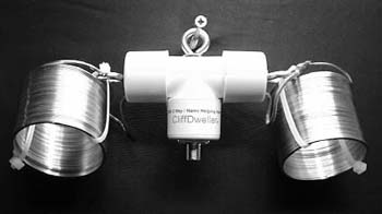 used,
of course, but this is pretty much a given for anyone attempting to use
a single antenna for multiple bands. The physical length of the wires,
if they were to be straightened out, is a full 130'. It is possible to
simply buy a 130' long wire antenna, but I love the whole idea of the Cliff
Dweller, and have no wish to try and find a 130' run for a wire antenna.
I purchased the antenna from USA2WAY over the net. There are some companies
which sell knock off units, but this is the original, and is claimed to
be the best, though others make their claims too. At any rate, the purchase
also gives me a membership, of sorts, in a user group, and access to a
number of technical resources.
used,
of course, but this is pretty much a given for anyone attempting to use
a single antenna for multiple bands. The physical length of the wires,
if they were to be straightened out, is a full 130'. It is possible to
simply buy a 130' long wire antenna, but I love the whole idea of the Cliff
Dweller, and have no wish to try and find a 130' run for a wire antenna.
I purchased the antenna from USA2WAY over the net. There are some companies
which sell knock off units, but this is the original, and is claimed to
be the best, though others make their claims too. At any rate, the purchase
also gives me a membership, of sorts, in a user group, and access to a
number of technical resources.
I am reasonably happy with the antenna. It performs well, across most bands, and it will have to do, for the present. My auto tuner seems a bit confused by it on some of the odd bands (12, 17, 30 meters), and takes a bit of time to tune to it on 10 meters. With a manual tuner, the antenna tunes right up on all bands, with no problem. The Cliff Dweller is strung along the ceiling of my apartment library, and is extended out to about 30'. I had considered running a length of wire, along the eaves of my apartment building, but did not wish to risk eviction from my building. This is the dilemma which most ham operators find themselves facing these days. It is not an easy matter to find space, and get permission, for a decent antenna, when living in an apartment, or condo complex. Though these places abound with power lines, TV antennas, and satellite dishes, most managers, and owners are poorly informed about ham radio, and find it easier to restrict, or forbid outside antennas for any such "non-standard" uses. The joys of city living.
Indoor antennas for the stealthy ham.
There are three things that can happen when matter and energy meet. Energy can be reflected, absorbed, or passed through. Most of us are familiar, or think we are, with the idea of radio waves either passing through, being absorbed by, or being reflected by the atmosphere. This is how shortwave works (or doesn't work), and how we make our long range contacts on HF. Certain frequencies are either absorbed by the atmosphere, reflected, or pass right through it. Ham operators obsess over MUF, critical frequency and other such things.
So what does this have to do with the properties of an indoor antenna system. Well, the same thing happens with the walls and roof of your house. They too have a MUF, reflect certain frequencies, absorb others and allow some to pass through. Unlike the ionosphere, we want as little interaction between the structure of our house as possible, while trying to transmit outside of it. Any interaction with the house structure will cause attenuation. How much attenuation depends upon the materials and construction of our houses, and the frequencies being used.
A good example of absorption is the common microwave oven. These usually operate at frequencies of 2.45 GHz (0.12 CM), though some operate as low as 915 MHz (0.33 CM). All of these frequencies are in use for radar and radio sets, and many ham operators are up in the higher bands, at or near these frequencies. Microwaves are radio waves, and exhibit the same properties. This includes the properties of attenuation, absorption, scatter, and reflection. The ability to interact with substances is why microwaves can cook.
Microwaves cook by dielectric heating. The most well know dielectric is water, though there are many others. Dielectrics have charged sections. Water has a distinct positive charge where the hydrogen atoms are attached, and a distinct negative charge on the portion containing the oxygen atom. When a water molecule is subject to an electric field, it will will rotate to align itself with that field. If the field alternates, as a radio wave does, the water molecule will rotate every time the field alternates. This does two things - it absorbs energy from the radio wave, and it creates heat. More accurately, it transforms radio energy into heat energy. Water does this particularly well, which is why radio is useless (with a couple of exceptions) underwater.
Microwaves do not cook from the inside, but appear to, because they can often cook food inside a container, without heating the container. This is possible, because microwave cookware is made from materials which do not interact well with radio waves. Glass, certain plastics, and many other materials are almost completely unaffected, and thus have little effect on radio waves which pass through them. In truth, microwaves heat at the surface of foods, only penetrating to the depth where they are fully absorbed. Lower frequency microwaves penetrate further. These two facts are of great interest to radio operators with indoor antennas.
Think about a bunch of mice, a herd of elephants, and a tribe of men walking through the forest. When all three are walking in open space, all three are passed. When all three come to a high brick wall, all three are reflected.
Lets say that all three come up against a thick wall of tangled jungle. The elephants crash through, using their great strength and power. The mice scurry through, using their size to get through the small openings. The men get stuck. They have neither the power to force their way through, nor the size to squeeze through. Though this sounds like another case of reflection, actually it is as close as I could come to an example of absorption. Pretty much all of the mice will get through, as well as all of the elephants. Some of the men might make it (pass through), some might just go back (reflection), but most will be tangled up in the jungle (absorbed).
Every material has its own absorption spectrum. Complex materials (like human beings) have an absorption spectrum which is the sum of the spectrums and interactions of the materials of which they are composed.
Scatter is a combination of reflection and passage - sort of like a pin ball knocking around inside of a pinball machine.
nothing is completely solid, in any real sense. Atoms are mostly empty space, and there is always more empty space between atoms. In addition to this, on our own scale, most things have cracks, holes, splits and other such imperfections.
Though it might not be intuitively obvious, in these examples, the elephant is an X-ray or gamma ray, the man is a beam of light, and the mouse is the radio wave.
Radio waves interact on either a molecular or electron shell level, depending upon the frequency.
Metals conduct because they have a structure in which they are essentially nuclei immersed in a communal sea of electrons. Since radio waves react with matter largely at the electron or molecular level, metal tend to reflect or absorb.
the reason that radio waves bounce off the ionosphere is that when the upper atmosphere particles become ionized, they exhibit many of the same properties as a metal - at least electrically. In both cases you have a loose collection of electrons floating around, that will gladly react with any electromagnetic radiation that comes their way.
standard wood building materials are said to have attenuation of about 4 db at 800 - 900 mhz.
motley keenan
In summary, anything down to about 20 meters will probably not be too bad inside of a normal structure. Anything down to 6 meters or so will probably be acceptable, but not great. Anything above that - good luck. In practice, my HF wire antennas are strung in my attic crawl space, my
A half-wave dipole is cut to length l for frequency f MHz according to the formula
 where l is in
metres or
where l is in
metres or
 where l is in
feet.[1]
This is because the impedance of
where l is in
feet.[1]
This is because the impedance of Dipoles are generally more efficient than whip antennas (quarter-wave monopoles). The total radiated power and the radiation resistance are twice that of a quarter-wave monopole. Thus, if a whip antenna were used with an infinite perfectly conducting ground plane, then it would be as efficient in half-space as a dipole in free space an infinite distance from any conductive surfaces such as the earth's surface
a vertical antenna will not generally couple to a horizontal antenna.
microstrip patch
helix
spiral
log periodic
capacitor plate dipole
glass comes from sand which is silicon - a semiconductor. Glass is definitely a conductor, which is why fiber optics work. Light is able to (mostly) pass through a pane of glass, because it is of such a high frequency, that it
A substance may be not transparent because it reflects the incoming light or because it absorbs the incoming light. Of course, almost all substances reflect a part and absorb a part of the incoming light.
Metals reflect most of the light because they have free electrons. These electrons are shaken by the electric field of the the light which is an electromagnetic wave. Shaken electrons emit two waves. One in the direction of the incoming wave that is seen as the reflected wave and one similar in the same direction as the incoming wave which, added with it, give a zero amplitude wave.
Dielectrics do not have free electrons. So the electrons bound to atoms are less shaken and reflect just a fraction of the incident wave. As the amplitude of the generated wave is less, there is a wave that enters the dielectric. We are talking about a transparent dielectric, as glass.
If you put colorant (dye) molecules in the dielectric, they will absorb the power of the entering wave. This power is transformed in potential energy that can transform in heat or even in other kind of light in some substances. The electrons in the dye absorb energy by climbing to higher energy states in the molecule.
A dielectric (even a black one) always reflects a part of the incoming light. If it doesn't contain light absorbent molecules (pigments, dyes, colorants), it is transparent.
Free electrons in a conductor can be considered as balls in a box. electric field "shakes" them, as I wrote. Said in a more correctly way: the electric field creates an alternating current in the surface of the metal. The frequency of this current is the same as that of the EM wave (light in this case). As in all real metals this current heats the metal and this corresponds to loses in the reflection. This is the reason why a metal does not reflects 100% of the incoming light.
An electron can not absorb light otherwise than increasing its energy. It is either as potential energy as in dyes, or as kinetic energy as in conductors.
If it is as kinetic energy, it accelerates and an accelerated electron radiates an EM wave as I told you before.
insulators are transparent, and conductors are opaque. This is why a faraday cage, a ground plane and a reflector element work.
There is quite a bit of confusion, contradiction, and misinformation out there. Some is sales hype, used to sell a certain product, or a certain approach. Much more is simple ignorance. The biggest myths out there concern multi band antennas, the use of baluns, and the efficacy of indoor antennas.
An SWR meter
An antenna bridge
Tubes vs. Wires
Shorter antennas, even when matched, become quite inefficient, quite quickly.
At 50% of a wavelength (half wave) theoretical efficiency could be as high as 100%
At 40% of a wavelength, system efficiency might typically be around 75%
At 35% of a wavelength, system efficiency might typically be around 55%
At 30% of a wavelength, system efficiency might typically be around 40%
At 25% of a wavelength, system efficiency might typically be around 22%
Below a quarter wave, efficiency drops off to nearly nothing, in a hurry.
Note that in every case, a properly matched system (for impedance) will show low SWR, even though efficiency of a smaller antenna will be quite low, and little of the power being sent down the line will be radiated as signal.
The light bulb example used earlier to demonstrate the qualities of radiators, reflectors and parasitical elements now comes back into play. A typical light bulb has an element several inches long, which is tightly coiled into a length of perhaps half an inch. It is fed through electrical wires which can be envisioned as twin lead feed line. Its hard to say what kind of an antenna you might compare this too, perhaps a folded dipole, since it is fed from both ends. At any rate, the filament is fed with a frequency of 60 Hz, by the local power company.
Doing the math gives a result that a 60Hz frequency would correspond to a 4,996,541 meter radio band. With 39.37 inches in a meter, the light bulb filament would have an electrical length of 1/380737 of a wave length, when considered to be a three inch elelemnt. This makes for an incredibly inefficient radiator of 60 Hz radio waves. s with any non resonant antenna, the wasted energy is transformed into heat. At first thought, it might seem that the light given off is some artifact or spurious radiation from the main frequency - it is not. The light is a secondary effect, occurring because the atoms in the filament have become so hot, that the electrons are continually raised to higher states, and then give off light as they drop back down to their base state. They would give off the same amount of light at the same frequency if they were heated with a torch to the same temperature.
Incidentally, a 60 Hz wave would be 3105 miles long, making for a 1552 mile long half wave dipole.
http://vk1od.net/antenna/G5RV/index.htm
This objective is best achieved with a balun with very high common mode impedance, a so called ‘current’ balun.