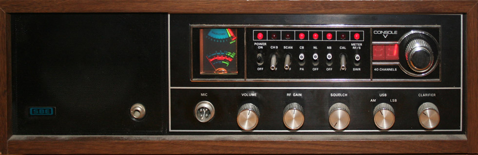
The SBE Console V
| Manual | Antenna | Specs |
| Repair | Mods | Links |
The Pinnacle
Hams do not generally give much thought to CB radio. Though many of us started off in CB, once we "Graduate" to that ham license, we let the CB gear go into disuse. It is a bit like a boy turning sixteen and getting that first driver license and first car. The old bicycle, once the most prized of possessions, suddenly finds itself abandoned.
Though this is not, strictly speaking, a ham radio, the Console was designed and manufactured by SBE (Sideband Engineers), which was an outgrowth of Gonset - a ham radio manufacturer. This was my first SSB base transceiver. It is a CB rig, but it is a deluxe one. This is sometimes also listed as the SBE Console 5. In its day (early to mid eighties) this was one of the best CB radios you could get – it still is. Along with the Trams, Brownings, and the legendary Stoner, this was a CB radio made to the same standards as a good quality ham radio.
This unit covers the 40 channel
27mhz band, formerly the ham 11 meter band. The band was taken from ham
operators, back in the fifties, and given over to the new Citizens Band
Radio Service. This was intended as a short range communication service
for the average citizen, who was not technically astute, and had no wish
to be. Power was limited to four watts, and usage was limited to short
duration, non business use. The service was also not to be for hobby use,
or for casual conversation. The initial intention was for the service to
be used for emergencies, or to enhance outdoor activities (hunting, camping,
hiking). A license was required, except for low powered units, putting
out less than half a watt. The service was soon dominated by kids with walkie talkies, and wannabe hams with base stations.
The "official" radio amateurs did not forgive the CB operators for decades -
some still haven't.
During the CB craze of the seventies/eighties, I purchased one of the
new 40 channel mobiles, and then picked up the Console V. I have had this unit
for almost thirty years. This was also when I began
to consider ham radio, and when I finally got my CB license. About four
months after I got my license, the FCC ruled that a license was no longer
required. The CB craze actually ruined CB. Such was the popularity, that
enforcement of rules became impossible. The service was left to unlicensed
operators, and restrictions are ignored, unless an operator interferes
with TV, radio, or some other service.
This was a pretty unusual unit, in terms of quality and features. Despite
the spirit and regulation against hobbyist use, this is plainly a radio for a
hobbyist, who takes CB radio very seriously. The unit has
a wooden case, a heavy duty metal chassis, and can be adjusted and peaked by the
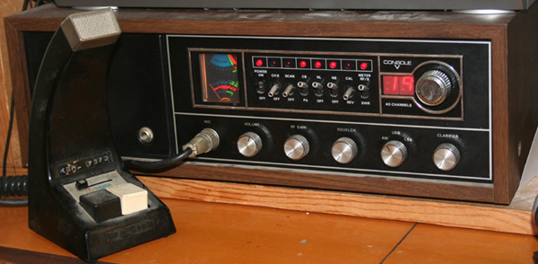
user. I immediately replaced the stock, mobile style mike, with a Mura, noise
cancelling, power mike. In its initial installation, this radio fed into a Starduster antenna, on a 20' mast, on the roof of our two story town house. On
top of all of this, we lived on a hill. I could get anywhere in the Milwaukee
metro area on that radio, with that antenna system. My range to mobile radios
was around 6 - 10 miles. I could hit other basses 30 miles away. When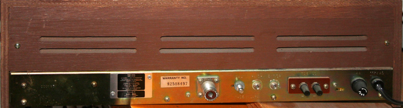 I was operating my
base, I used the handle of Starbase, both because of my Starduster antenna, and
because I was a bit of a Star Trek enthusiast - hey, it was the late
seventies/early eighties, and I was still in my teens.
I was operating my
base, I used the handle of Starbase, both because of my Starduster antenna, and
because I was a bit of a Star Trek enthusiast - hey, it was the late
seventies/early eighties, and I was still in my teens.
For seventeen years, I lived in an apartment on the
East Side of Milwaukee. I was unable to use the Starduster antenna at that
location, and instead used a 5/8 wave groundless antenna, meant for marine use.
This antenna was mounted on an outside balcony rail, and gave great service from
my third floor apartment,
though not as good as that given by the old Starduster. At my current location,
I use a home made wire antenna. it is of groundplane design and is mounted in my
attic crawl space. This is presently the largest of all of my antennas, or at
any rate the most obtrusive.
 The Console V is a forty channel unit, which is capable
of being used in AM or SSB mode. The SSB mode gives it a practical selection
of 120 channels. Transmitting on the sidebands also triples the effective
power of the transmission. This was one of the more expensive CB radios on
the market, and was up to the quality of many of the better ham radios.
It has a number of scan, and program features, and has built in indicators
for SWR, as well as transmitted, and received power. The transmit and receive
are excellent, as is the construction of the unit. This was a product of
the heyday of CB radio, when it's popularity caused it to be taken very
seriously by equipment manufacturers. The unit can be operated on 12 volts
or off of household current.
The Console V is a forty channel unit, which is capable
of being used in AM or SSB mode. The SSB mode gives it a practical selection
of 120 channels. Transmitting on the sidebands also triples the effective
power of the transmission. This was one of the more expensive CB radios on
the market, and was up to the quality of many of the better ham radios.
It has a number of scan, and program features, and has built in indicators
for SWR, as well as transmitted, and received power. The transmit and receive
are excellent, as is the construction of the unit. This was a product of
the heyday of CB radio, when it's popularity caused it to be taken very
seriously by equipment manufacturers. The unit can be operated on 12 volts
or off of household current.
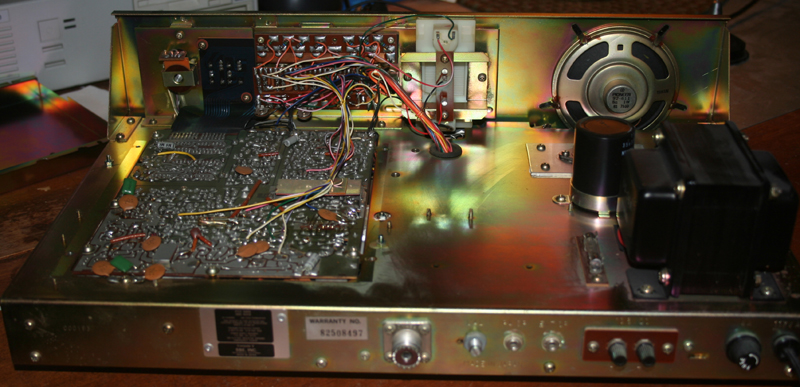
Inside, the unit shows
its high build quality, and the robust design. The unit has a true metal
chassis, not just a circuit board with some framing. It is also designed from
scratch as a base, and is not merely a mobile unit put in a big box (though the
PLL and some of the other modules reside on a board that would fit in a standard
mobile case). The power supply is massive, which would seem to indicate the
potential for replacement of the finals with something more powerful. More
interesting is the possibility of using some of the empty space inside the case
for installation of a small linear, powered off the built in transformer.
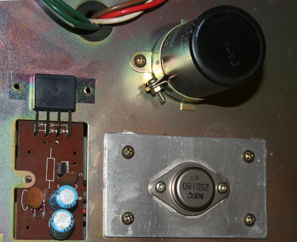
The final itself is mounted on a large aluminum plate, which acts as a heat sink. It sits just behind the speaker, and there is more than enough room for a much larger sink. The final used is the now discontinued NEC 2sd180. This final is rated at 60 watts, with a suggested range of 30 to 60 watts, depending upon application. It is no longer available, but replacements are the 2sd428, and 2sd1485 - both rated at around 80 watts. These conservative ratings make for a long life, and for the possibility of raising transmitter power by simple tweaking of the unit.
I have considered replacement with a 2sd428, and the addition of a second 2sd428 on a separate board, using some of the empty space in the case. This second board could be switchable. Switched on, this would give the potential of an honest 80 watts conservatively driven, or over 100 watts of RF fully driven. Another possibility would be to replace the current final with a 2SC2879. This would give a possible 65 watts on AM and 100 watts PEP. It would also be easily possible using current wiring and power supply.
The final is mounted next to its drive, with a large electrolytic capacitor, presumably used as a filter. These are shown in the photo to the right. A small metal retaining unit has been removed from the driver, so that it can be seen better in the photo. These are all mounted rather close to the transformer, so that the major heat producing components are away from the rest of the circuitry. This would also be a natural place to put a cooling fan. If I were to add a linear, this is the area in which it would be mounted. Right now, none of this is worth the bother, or the possible legal issues. If I want to talk using higher power, I can fire up my TS-440 on ten meters and use 100 watts.
CB operators are always talking about "getting out" and increasing power. With a 4 watt limit on power, many are willing to skirt the law and purchase gear of questionable utility. An illegally manufactured or modified linear is unlikely to honestly advertize its capabilities, and is even less likely to have a warranty. Though many CBers are willing to spend great amounts of money on radios, amplifiers, power mikes, and other such things, most do not pay much attention to their antenna systems. This is a shame, particularly for those few CB operators who still run base stations.
Ham operators are almost exactly the opposite. Though many of us have powerful (and legal) linears, as a group we are quite obsessed about antennas. So while you see lots and lots of interest in experimentation with various antenna types among ham operators, you see almost none in the CB world. CB antennas are almost all quarter wave whips, helical wound or loaded verticals, or classic ground plane verticals.
CB has a fairly low frequency, compared to the FRS/GMRS radios so many of us are using these days. This calls for a rather long antenna. Doing the math, you get a quarter wave radiator length of 8.61 feet, which comes out to a bit over 102". This is the traditional length of a quarter wave whip for CB, though most need to be tuned or trimmed due to coax velocity factor, and installation variance.
The 102" length is way too long for the attic crawl space in which I grow my antenna farm. In addition, one of the dirty little secrets of the popular and common quarter wave antenna is that, of itself, it is only 22% efficient. In base antennas, this is usually dealt with by setting up a ground plane of horizontally oriented, quarter wave radials. It is also possible to construct a half wave vertical dipole, though you are talking a sixteen foot long antenna that is likely to be greatly affected by its height above ground. In mobile installations, the car body or some other surface is used as a ground. These are attempts to make the quarter wave antenna appear to be a half wave unit. Effectiveness varies. The goal is to make an antenna that emulates a half wave radiator, which has a theoretical efficiency of 100%.
My situation does not allow for a large roof mounted antenna. That's right, I am a stealth operator. As a CB operator, I might consider the old classic magnet mount stuck to a refrigerator or baking pan. Or I might consider one of those ghastly back of the set antennas. Still, when you are using such a limited power system, and have no legal options to raise power, the antenna options become far more important.
Let's look at some math, and prepare to be horrified. A half wave antenna has the potential to be 100% efficient, if everything in the system is perfect. A quarter wave antenna has the potential to be 22% efficient, which also never happens. Now a quarter wave can become more efficient by being driven against a ground. In the case of a base antenna, this ground might be a set of radials, called a ground plane. In the case of a mobile antenna, it might be the body of the car. What the ground does is mirror the antenna, so that a quarter wave can "look" like a half wave. Of course, this is never completely efficient, and a quarter wave with ground will be lucky to be 50% efficient. Over a poor ground, there will be little or no improvement over the base quarter wave radiator.
Another problem, particularly in mobile use, is that many "quarter wave" radiators are not really quarter wave. I have seen a considerable number of mobiles antennas that are 40" or less in length. Loading coils, and other such things, can make them appear to be the correct length electrically, by providing the correct impedance; but they do nothing to bring up the efficiency of the radiator. So a 40" radiator with a perfect ground will only be about 20% efficient, and likely the number will be much lower.
So what kind of antenna do I have, and how well does it work?
After considering various squalos, loops, helicals, traps, and loaded antennas, I decided upon a folded loop. Such an antenna is not terribly small; but it is small enough. It is also not terribly efficient; but it beats the alternatives, and certainly beats the usual loaded, trapped, and modified mobile antennas usually used in stealth installation. Again, it is efficient enough. It measures out to be a rough cube about five feet tall, by a bit over three feet wide, and three feet deep. I have a couple of other folded dipoles; but they are made of copper pipe. This particular example is made of wire. it is so constructed so that I can run it half in my attic, and half in part of the second floor of my townhouse. this keeps it hidden, and allows it to be the length that it requires.
The antenna is
omnidirectional, and essentially vertically polarized, though the folded
elements do offer some horizontal polarization of the signal. The SWR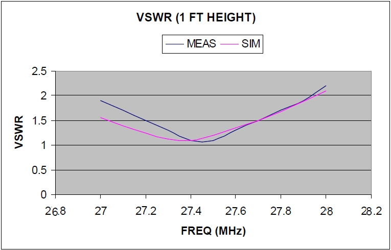 plot at right indicates that I probably should have made the antenna just a tiny
bit longer - a matter of a few inches; but it is more than good enough, and the
SWR never really goes above 1.5 on the desired frequencies.
plot at right indicates that I probably should have made the antenna just a tiny
bit longer - a matter of a few inches; but it is more than good enough, and the
SWR never really goes above 1.5 on the desired frequencies.
Other than the
rather large size, CB is not particularly demanding upon an antenna. The
bandwidth required is about a half megahertz, which comes out to be
about 2% of the base frequency. So if you tune for the center of the band, you
will never be more than 1% off from the center. The antenna works well enough,
is reasonably efficient, and gives good SWR. More details will be given on my
antenna page, if I ever finish it. Attenuation through the walls of my attic
(this is an indoor antenna) appears to be minimal, which is not a surprise at
these frequencies.
|
Model |
SBE Console V |
|
Frequency Range |
26.965 - 27.405 MHz (40 Channels) |
|
Emission Modes |
AM/USB/LSB |
|
Frequency Control |
Phase Lock Loop (PLL) Synthesizer |
|
Frequency Tolerance |
0.005 %** |
|
Frequency Stability |
0.001 %** |
|
Operating Temperature Range |
-30°C to +50°C** |
|
Microphone |
Dynamic PTT, 500 Ohms |
|
Input Voltage (DC/AC Selectable) |
13.8V DC / 110V AC 60Hz |
|
Current Drain: Transmit (AM full mod.) |
< 3.5A** |
|
Current Drain : Receive (Squelched) |
£ 0.5A** |
|
Current Drain : Receive (Max. audio output) |
< 1A** |
|
Antenna Connector |
UHF; SO239 |
|
Dimensions |
6"H x 18"W x 12"D |
|
Weight |
12 lb.** |
|
TRANSMITTER |
|
|
RF Power Output |
AM : 4W / SSB : 12W PEP (NEC 2sd180) |
|
RF Transmit Modes |
AM/SSB |
|
Modulation |
High and Low level Class B, Amplitude Modulation : AM and SSB |
|
Spurious Emissions |
-60 dB** |
|
Carrier Suppression |
-60 dB** |
|
Audio Frequency Response |
300 to 2500 Hz** |
|
Antenna Impedance |
50 Ohms |
|
Output Indicators |
Meter shows relative signal strength, RF output power, SWR and AM Modulation level. Transmit LED glows red when transmitter is in operation. |
|
RECEIVER |
|
|
Sensitivity for 10dB S/N (AM/ SSB) |
< 0.5 mV / < 0.15 mV** |
|
IF Frequency |
AM: 10.695 MHz 1st IF, 455 KHz 2nd IF |
|
Image Rejection |
-50 dB** |
|
Adjacent Channel Selectivity |
-60 dB** |
|
RF Gain Control |
45 dB adjustable for optimum signal reception** |
|
Automatic Gain Control (AGC) Figure of Merit |
100 mV for 10 dB Change in Audio Output** |
|
Squelch |
Adjustable; threshold less than 0.5 mV** |
|
Noise Blanker |
RF type** |
|
Audio Output Power |
2.5W @ 10% THD** |
|
Audio Frequency Response |
300 to 2500 Hz** |
|
Built-in Speaker |
8 Ohms, 4 Watts** |
|
External Speaker (Not Supplied) |
8 Ohms, 4 Watts** |
After a number of years of storage, I found there was no modulation on transmit. The radio received fine, and was able to generate a good strong carrier; but no modulation occurred. This did not come as a complete surprise. The SBE radios, like much electronic gear made in the early eighties, were susceptible to failure of electrolytic capacitors after a few decades. SBE also had a bit of a reputation for cold solder joints. These conditions can create unpredictable and sporadic failures. Fortunately, the solution is simple. Capacitors are cheap, so just replace them. Solder joints can be checked. While I was in the radio, I also gave it a good cleaning.
The repairs took an entire day, though the actual replacement took under an hour. I first photographed all boards and internals, and then began to snip the electrolytic capacitors from the board, rather than desoldering. This left a bit of the connecting pins, which I used as solder points for the new capacitors. A set of schematics, along with the photos I took, were of great help. Having removed the caps, I verified their values, and then got a new set for a few dollars. For those who wish to do the same thing, I have included photos, schematics, and a parts list.
With the caps replaced, the radio works perfectly. Occasionally, resistors and other components might also need replacement; but the caps are always the first things I check. In addition, resoldering of any joints that appear dull or flaked, and a good general cleaning of switches and connectors, completes the job. This would also be the time to add any new features or do mods - legal or illegal.
With such a large case, and so much empty room (see photographs) it is tempting to add all kinds of different things to the radio. In my own case, I considered replacing the finals, adding a frequency counter, and installing an "On The Air" light. The On The Air light is very stupid; but I may yet do it. The other mods will not be done. One of my early CB radios was a Radio Shack Navaho TRC-431. It was a simple radio, AM only, without a lot of features; but it did have a green "On The Air" light, and a companion Modulation light. As a teen ager, I thought this was the last word in radio eye candy.
Extra channels/Increased power
(breaking the law, and wrecking your radio)
Though I wanted to make this the ultimate CB radio, I have no interest in adding extra channels. Besides being illegal, there is no need for them. There are not many people to talk to on these channels, and the band crowding of the old days of CB is long gone. When I want to talk on other channels, or with significantly more power, I turn off my CB and fire up one of my ham radios. In addition, in this particular radio design, the mod is more trouble than it is worth.
Frequency mods, also known as extra channels, are possible, though not as easily accomplished as on some models. The Console V uses a pair of chips as a PLL to synthesize frequencies. The MC14526 is a 4bit ÷N programmable counter. The MC14568 is a phase comparator/programmable binary counter. Combined they make up a 8 bit binary counter. In latter designs, these chips were replaced by a single NDC40013.
While some radios, notably the old Cobras and many Radio Shack models, were easy to modify, the SBE is not. Rather than simply shorting together pins on the PLL chip, the SBE radios require a pair of switches and a bit of wiring, to remix the crystals in the mixer. This gives 82 extra channels (for a total of 122), and essentially continuous coverage from 26.520 to 27.725. Instructions for doing this can be found all over the web. Since I have not performed this mod, I have not included the instructions. Please do not send me emails asking for advice on how to break the law.
CB radio was, and to an extent still is, notorious for having guys run more than the legally allowed power. Largely this is due to the 4 watt limit, which just seems to gnaw at the vitals of many ratchet jaws out there. Most often this was done by purchasing or building linear power amplifiers. sometimes it was accomplished by modifying 10 meter ham radios, which are designed to put out more power, to run on the nearby CB frequencies. There were also some users who would have their radios "tweaked".
The Console 5 lends itself readily to being tweaked, though there are a number of good reasons not to do this. The power transistor, also known as the final, on this radio is an NEC SD180. This transistor is rated for a power of 60 watts, and is run at much lower power. A tweak would bring the power up to the full rated 60 watts. The problem is that as a transistor is run near its capacity, it runs hotter, and becomes far more sensitive to SWR, and overloading.
It is possible to replace the finals on your radio. You may use a higher power unit, or even add dual finals. Galaxy sells kits to do this to their radios. This is easier to do than you might think, as long as you keep your expectations reasonable.
Still, for anyone tempted to add extra frequencies or run at higher power, I strongly recommend getting a ham license. This license will allow you to legally talk on the nearby 10 meter band, which is where many of the "extra" channels on CB are located. With a ham license, you will be able to legally use up to 1500(!) watts. You will also be able to use many other bands at higher and lower frequencies. Code is no longer required. you simply take a test on some basic radio theory and regulations, and are issued a license. C'mon guys; don't be so lazy. Just do it.
There is not really very much information out there about these great old radios. This is a shame, but not a surprise. I picked my radio up new in 1977. This is the only production year given, and it is possible these were not made for very long, or sold in very great number. I paid a bit over $200 for mine, and I recall that the guy who sold it to me got into a bit of trouble with his boss, because he gave it to me at dealer cost. These were typically selling for $300 - $400 back in the seventies.
| CB Tricks | |||