The Midland Syn-Tech XTR
70-1630B
| Manual | Antenna | Specs |
| Repair | Mods | Links |
Top Drawer
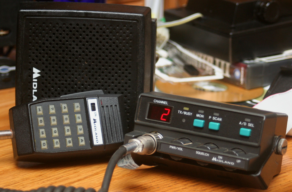
This is the UHF version of the Midland XTR PS/PB band FM radio. It is my second XTR radio, my first being the 2 meter VHF version. Much of what I said about the 2 meter version applies to this model, and I suggest reviewing its page for the basics. Both were put into service in the late 90's/early 2000's. Most have been removed from service for about ten years. Versions were also made covering frequency ranges that can be adapted to 10 meter and 6 meter.
 This unit originally put out 30 watts on 22 channels. it has
had several options added, to greatly increase its capabilities. The most
important is the tone board. With it, this radio can access repeaters and work
splits. This unit also has the 99 channel upgrade, though it is presently only
using 23 channels, and two of those are for receive only weather. The unit
appears to be adaptable to FRS/GMRS frequencies, and I will eventually attempt
to add these to the current channel programming. I will update this page with
the results.
This unit originally put out 30 watts on 22 channels. it has
had several options added, to greatly increase its capabilities. The most
important is the tone board. With it, this radio can access repeaters and work
splits. This unit also has the 99 channel upgrade, though it is presently only
using 23 channels, and two of those are for receive only weather. The unit
appears to be adaptable to FRS/GMRS frequencies, and I will eventually attempt
to add these to the current channel programming. I will update this page with
the results.
Though not enjoying the popularity of 2 meter, 70 cm is the most popular second band on multi band portable radios. This can be an advantage, and I have noticed that I often have the band much to myself, and to the small circle of friends I like to talk to. Additionally, the 70 cm band, with its 30 MHz band width, has a wider range of frequencies available than that of all the HF bands combined. It is a wonderful band for experimenters. There are regular fast scan television, satellite, moon bounce, and digital modes. Yet these are not available to the Midland XTR. The most popular use of the 70 cm band is standard FM transmission, most often through repeaters. This is where the Midland shines.
There is an old joke about some things being designed by geniuses to be used by idiots. This radio is completely channelized and has no user accessible adjustments. There is no tuning by frequency, and no frequency display. Offset is programmed in and inaccessible to the user. Filters are set at the factory or by radio techs. There are no dials to fiddle with other than volume, squelch, and channel. There are no buttons to play with other than a very basic scan, and a monitor button which allows the user to listen in on the transmit side of the offset (a talk about function). A technophile ham who likes to tinker and tweak will not like this radio. The rest of us will love it.
Though designed as
mobile radios, these units make great FM base stations, and are sought after by
repeater builders. The disadvantage for base use, is the channelization, which
allows them to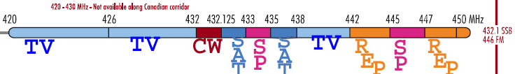 only work certain frequencies without being reprogrammed. They
are also FM only, though this is not unusual for UHF radios. I presently own one
base, one mobile, and several handhelds that operate on this band; but I could
not resist acquiring this unit. The limited channel range is not such a handicap
when used in this fashion.
only work certain frequencies without being reprogrammed. They
are also FM only, though this is not unusual for UHF radios. I presently own one
base, one mobile, and several handhelds that operate on this band; but I could
not resist acquiring this unit. The limited channel range is not such a handicap
when used in this fashion.
According to the 70 cm
band plan, frequencies from 420MHz - 426 MHz are reserved for amateur fast scan television, as is
the range from 438 MHz - 442 MHz. Other segments are reserved for CW, and
satellite. What is left for regular FM communication is a 4 MHz band for simplex
(non-repeater), and a pair of 3 MHz segments for repeater use. This comes out to
160 possible simplex 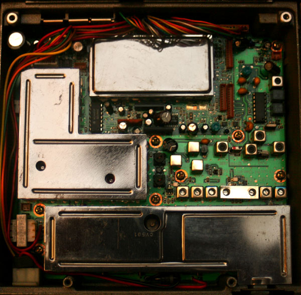 frequencies, and 120 possible repeater frequency pairs.
Most areas have a half dozen to a dozen repeaters, leaving about 90 channels left for the 160 possible simplex frequencies. This is not a huge handicap. With the ultimate 320 channel option (mine only has the 99 channel option), There would be 40 extra channels, presumably to be used for GMRS/FRS. This opens the exciting possibility of using this radio with non-licensed friends and family on GMRS frequencies. I am not certain of the legalities of this; but it is physically and electronically possible.
The modular construction is ideal for police use; but can be somewhat of a handicap for civilian installations. The control head is small; but is not complete. A place must also be found to mount the speaker. Additionally, a ribbon cable must be run to the main unit, as well as power connectors.
My first attempt at installation in my car was frustrating. A full sized car would likely make for an easier install. Unlike standard installation of a dash mounted radio, a modular install takes a bit of planning. This is particularly difficult in certain models of car, like mine, which have the battery inaccessible within a wheel well. Transmitting at full power, the unit can draw 8 amps, so heavy gauge wire connectors must be used.
These radios are heavily built, and weatherproofed. As can be seen in the photo to the left, the internals are fully shielded, and well spaced for cooling. Shielding helps with RFI, and also quiets the internals. It is a simple enough concept, but often skipped on consumer grade radios due to the difficulty of adapting automated manufacturing processes to the placing of shields. Note the holes in the shielding to give access to certain adjustment points with the shields in place.
The bottom chassis
is massive and ridged to double as a heat sink. Cooling is important in a
commercial radio designed to be used daily with a high duty cycle at an output
of 30 watts. These radios are built to mil-spec, and are designed to operate
with damaged antennas, and reduced voltage power supplies. This is not a hobby
radio. This kind of unit is designed for absolute dependability for the user who
may one day call upon a radio for his life.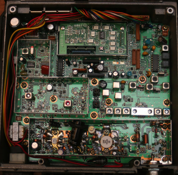
A look under the hood, with the shielding covers removed, shows a basic similarly to the 2 meter version, with a few variations, and some differences in the output amp stage, in the lower right of the photo. A look at the center top section shows both the CTCSS and 99 channel memory expansion installed - almost a given in a used radio. These were such necessary and popular options that it is rare to find a radio not equipped with both. Still, when buying one of your own it is best to make certain. Many resellers remove these options and sell them separately.
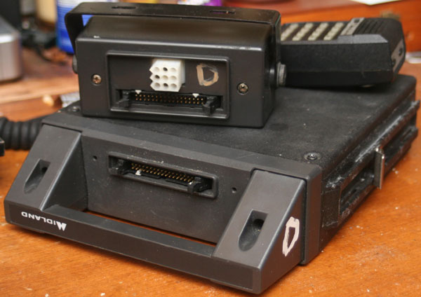
Programming, in the XTR and later versions, is accomplished through a 10 pin port located on the bottom of the radio. It is sealed by a small rubber plug. A special adapter cable is needed to convert the signals from standard TTL to com, and then to adapt the 10 pin port to the standard computer com port. Software is required, but widely available. Motorola has its own proprietary software, or you can go with something universal like RadioPro. The units were originally designed to be programmed through a com port, rather than today's more common USB port. Both Windows and DOS programming software is available. Earlier versions of the radio required a special programmer or an EPROM programmer.
It is possible to run this radio directly from a computer, and there are adapters and software available to do this. As the head has full audio and control access to the radio, an adapter for a com port or USB port would permit computer control with appropriate software. It should also permit the use of multiple radios as computer controlled repeaters. This is something I am looking into, as at their current very low prices, a capable reaper with a good deal of power could be configured for relatively little money.
A look at the inside shows that this is an easy to configure, easy to service, and easy to upgrade radio. It is ideal for high duty cycle repeater use.
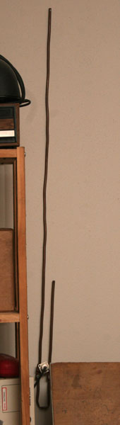
70 cm is a wonderful band to make antennas for. A half wave dipole is about a foot long. A great Slim Jim or J-Pole antenna with lots of gain is about a foot and a quarter long, and can be hung on the wall. A standard two meter antenna can be used for 70 cm, as it is the third harmonic; but I prefer to use separate antennas due to the strange affect of such an antenna on the signal pattern of 70 cm. For indoor use, I have a Slim Jim, my favorite type of VHF/UHF antenna. A standard magnet mount antenna is more than sufficient for mobile user, particularly when putting out over 30 watts on channels served by repeaters.
Radio operators have made Slim Jim antennas out of bits of twin lead; but I prefer flexible copper tubing. It holds its shape better, and that extra diameter gives just a bit more bandwidth. This is a vertical antenna, and though there is some use of horizontal polarization on 70 cm, this is on SSB or AM for working satellite and bounce, and is never used on FM. The antenna was easy to make, and hangs on the wall of my shack, just a few feet from my radio to keep the feed line length (Critical at these high UHF frequencies) short.
This band is very close to the GMRS/FRS band used for the VHF CB service. As such. commercial antennas for that band may be used as well. There will be more details on my antenna pages, if I ever get them up. In the meantime, commercial or home built antennas are very small, cheap, and easy to install for this band. I had initially made up a classic ground plane antenna, which was for a short time used also on my Kenwood TS-811; but a Slim Jim or J-pole is so easy to put up, and has so many advantages, that there is little point in playing around with a ground plane at these high frequencies.
|
Model |
70-1630B |
|
Frequency Range |
450MHz – 470MHz (typical) |
|
Emission Modes |
FM (160KF3E 5KHz) |
|
Frequency Stability |
.0005% |
|
Operating Temperature Range |
-30 to +60 C |
|
Microphone |
6 pin |
|
Input Voltage (DC/AC Selectable) |
13.8V DC |
|
Current Drain: Transmit |
8 amps |
|
Current Drain : Receive (Squelched) |
0.3 amps |
|
Current Drain : Receive (Max. audio output) |
1 amp |
|
Antenna Connector |
UHF; SO239 |
|
Dimensions |
Remote-mount 2.25 x 7.75 x 9.72 Control Head 2.25 x 4.75 x 3.31 |
|
Weight |
Main unit 6.1 / Control Head 0.8 |
|
TRANSMITTER |
|
|
RF Power Output |
30 Watts |
|
RF Transmit Modes |
FM (160KF3E 5KHz) |
|
Spurious Emissions |
|
|
Audio Frequency Response |
|
|
Antenna Impedance |
50 Ohms |
|
RECEIVER |
|
|
Sensitivity for 10dB S/N (AM/ SSB) |
|
|
Image Rejection |
|
|
Selectivity |
|
|
Squelch |
|
|
Audio Output Power |
10 watts |
|
Audio Frequency Response |
|
|
External Speaker |
8 ohm |
Repair/Mods
Extra channels/Extra Features
Lots of mods on these radios - too many. That is probably one of the reasons for their popularity. As police/commercial radios, these were modular in construction, and could be ordered to suit the needs of the operator. They were available with anywhere from 8 to 99 channels, and there is at least one aftermarket company that produces an add on module that will bring the channel count up to 320. Encryption and trunking boards were available, as well as repeater (store and retransmit) and tone options. A tone burst board (now largely obsolete in the U.S.) was available, as well as a DTMF decoder. The most common and necessary option is the CTCSS tone board.
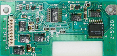
An uninstalled CTCSS board is shown in the photo to the left. The same board can be seen in the photo of the inside of my radio; but the installed board is face down. These can be somewhat difficult to find; but the good news is that most of the radios you will find already have these installed. The notch visible at the bottom of the board, is to allow insertion of the 99 channel upgrade on the main board of the radio. Once the tone board is installed, tones are selected during programming. This board is capable of decoding on receive as well as encoding on transmit.
The Midland 70-2180, 99
channel upgrade is nothing more than a set of memory chips to enhance the on
board memory, and hold the additional channel information. These are very
similar to computer memory modules, and can be user installed by snapping them
in. They install under one of the RF shields near the CPU of the radio main
board. A notch in the CTCSS board allows both options to be installed. A photo
of the memory modules is shown to the right. Three are in the photo; but only
one is installed on the radio. This particular radio has both of these options
installed,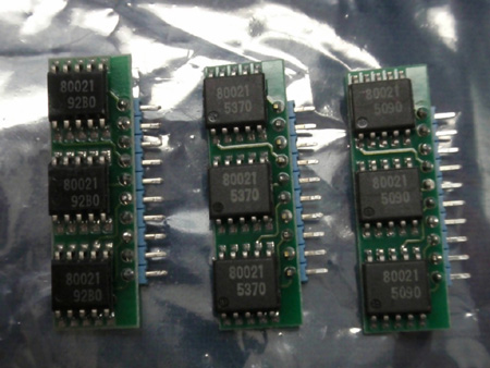 as well as the scan option.
The scan option is nothing more than a bezel with a scan button and a new trim. It allows scanning of the entire range of channels, or of specific banks set during programming. Software, circuitry, and memory for this is already present on the motherboard. Only the button is added in the upgrade. This offers some interesting possibilities to those attempting to computer control these units.
Other interesting options are a weatherproofing kit, a 2.5 ppm frequency stability kit, and an assortment of speaker and microphone options. All of these radios are available as all in one units, or as remote trunk mount units. Various mounting and cabling options are also offered.
Because these are
programmable radios, any frequency within the programming range may be selected,
though the range can affect transmitter power.
Frequencies within 10 MHz of a user selected central frequency will have a
transmitter power of 40 watts. Frequencies within 24MHz will have 30 watts of
transmitter power. The manual indicates four frequency ranges for this
particular model - 403MHz – 430MHz (A), 450MHz – 470MHz (B), 470MHz – 500MHz
(C), and 490MHz – 520MHz (D). You might notice that the A range is good for 70
cm, and the B range is ideal for GMRS/FRS, and pretty good for 70cm. These
bandwidths can be extended through the programming and will program out of
range. The VCO usually requires adjustment when the radio is programmed out of
the factory frequency range. VCO unlock is indicated by E3 blinking on the
display and an alert tone. I have had no issues with this on 70 cm or GMRS; but
due to the band plan, I have not needed to program down past 440MHz, and would
never need to go down past 432MHz. Note that there is no variation which ideally
suits 70cm. There is no reason for one, since this was designed and manufactured
as a PS/PB radio rather than a ham radio. .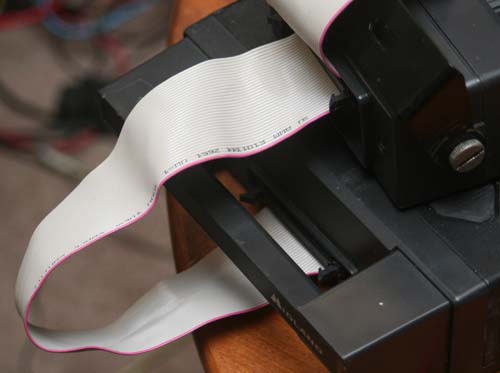
If you can not find the 16' - 20' 34 pin cable made for this radio, you can use a standard floppy cable instead, though please note that this only works for the XTR version of the radio. Floppy cables can be handy because they are relatively cheap, since no one really uses floppy drives any more. They are also short, typically only a few feet. This can be handy for base use, if you do not want to deal with stowing the extra length of cable. Floppy cables generally cost a dollar or two. Syn-Tech cables in standard lengths are around eighteen dollars, though you can get a shorter cable for around eight dollars.
For those not familiar with them, a floppy cable will have a single connector at one end, and a pair of connectors close together at the other. On the end with the two connectors, one of those connectors will have a twist in a portion of the ribbon cable. For use with this radio, you will want to plug the single connector end into the base unit, and the non twisted connector on the other end into the control head. Make certain both ends of the cable are securely connected, and lock them in. The cable ends are keyed, and by good luck, they match the keying of the radios.
On my personal; radio, when used as a base, I have cut the second connector off the dual connector end. This makes for a more manageable install, and makes it impossible for the wrong end to be connected.
These commercial radios can sometimes be confusing to buy when found on ebay and other such places. You will see control heads, main units, and all kinds of other things with dire warnings that this is a part of a functional radio, but will not function by itself. Advertisers will then talk about low band, high band and other such things, making it even more confusing. The first thing you probably want to do is figure out which model is useful on the frequencies you want. A guide to the frequency ranges of different models can be found here.
You get to the point where you do not know what you are buying, if you have everything, and if it will all work together. Many people selling this gear don't know what they are doing, or in some cases intentionally break units up and sell components separately to make more money. I have seen radios that will work (or can be realigned to work) on 10 meter, 6 meter, 2 meter, GMRS, 70 cm, and VHF marine. I am trying to verify rumors that these are also programmable for 12 meter, and 900Mhz.
The following are what you absolutely must have for a working radio - control heads and remote units must be of same model:
-
Control head
-
Microphone (sometimes, but not always, included with control head)
-
Main unit (sometimes called the remote unit)
-
34 pin ribbon cable to connect XTR control and radio units (37 pin cable for Syn-Tech II)
-
External speaker with connector
-
Power connector for remote unit
-
Antenna (any standard antenna for the band)
-
If used as a base, you will need a 13.8 v power supply.
Desirable features on the radio will all be found in the remote unit. These features are:
-
CTCSS board
-
99 channel option (or better)
You will also need a programming cable and programming software, unless you purchase the unit from a tech or shop that will program it for you. I purchased my radio for $35 from a local ham operator and radio tech who programmed it for me with all the local repeaters, and a few of the more popular simplex frequencies. I consider this to be a great bargain. You may do better or worse on the net or at local swap fests.
Installation is a bit more complicated than your basic all in one unit; but also offers some flexibility. My remote unit is installed under the passenger seat, with a coax running to an antenna mounted by the trunk, and the control head mounted in an opening in the dash. Installation only took a couple hours, and could have been done faster; but it took me a while to decide not to mount the remote in the trunk, which is traditionally where they are mounted. The control head is small enough that I can actually mount two of them (2 meter and 70 cm) side by side in the dash opening which originally held my old CB radio. I will update with photos of the install when I have time.
Schematics are available on some of the sites listed below, and offer the potential of creating a custom interface, feeding off the ribbon cable to the control head, for computer control of the radio. I am wondering about the possibilities fo multiple radios running off the same computer, permitting multi band operation, or perhaps even configuring as a repeater. It also gives potential for unlimited scanning memories and banks, as well as digital recording and logging. Once you get one (or more) of these things into the computer, it's just a matter of the imagination of the programmer.
Similar offerings from Motorola and G.E. are probably just as good; but due to the popularity of these brands, are probably more expensive. Midland does have a number of newer commercial radios out there, offering more channels, and more digital features; but they are also more expensive. A newer Titan style Midland radio is about four times the cost of the Syn-Tech, and to my mind does not offer sufficient additional features to justify the additional cost, to most amateur operators.
These were very popular radios, and there are a number of links and resources on the web. The entire Syntech line is treated as a single radio, most places. So I advise the interested user to check the links on my Syntech 2 meter page.
| Programming | |||||||
| While this radio has the 99 channel option, I only have these 23 channels programmed at this time. This covers most of the local (SE Wisconsin) repeaters, as well as some popular simplex frequencies. I also have the weather band programmed for receive only. | |||||||
| CHANNEL | RX | TX | TONE | CHANNEL | RX | TX | TONE |
| 1 | 444.450 | 449.450 | 127.3 | 13 | 443.550 | 448.550 | 127.3 |
| 2 | 444.450 | 444.450 | 127.3 | 14 | 443.800 | 448.800 | 123 |
| 3 | 444.625 | 449.625 | 127.3 | 15 | 443.950 | 448.950 | 127.3 |
| 4 | 442.350 | 447.350 | 123 | 16 | 444.850 | 449.850 | 127.3 |
| 5 | 444.200 | 449.200 | 127.3 | 17 | 442.675 | 447.675 | 127.3 |
| 6 | 442.850 | 447.850 | 88.5 | 18 | 443.050 | 448.050 | 127.3 |
| 7 | 442.100 | 447.100 | 127.3 | 19 | 443.300 | 448.300 | 127.3 |
| 8 | 442.875 | 447.873 | 127.3 | 20 | 443.525 | 448.525 | 114.8 |
| 9 | 444.525 | 449.525 | 114.8 | 21 | 443.750 | 448.750 | 127.3 |
| 10 | 444.275 | 449.275 | 127.3 | 22 | 446 SIMPLEX NO TONE | ||
| 11 | 442.425 | 447.425 | 127.3 | 23 | 446 SIMPLEX NO TONE | ||
| 12 | 4443.325 | 448.325 | 127.3 | ||||