The Kenwood TS-711
Multimode 2 meter transceiver
| Manual | Two Meter | Antenna Systems | Factory Specifications |
| Modifications | Computer Interfacing | Repeaters | Links |
Once upon a time, two meter was taken pretty seriously. There were many
operators who attempted to work DX, QRP, the occasional skip, and of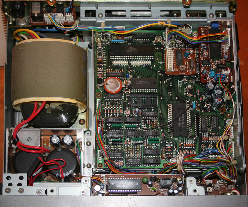 course
worked all the local repeaters. Not any more. Today, two meter has degenerated a
bit, becoming a sort of a licensed, grown up version of what CB once was. This
is not necessarily a bad thing. I enjoyed CB decades ago (still do to a certain
extent, particularly if I want to talk to unlicensed friends), and I have
enjoyed my share of casual talk, and late night involved conversation on two
meter. Some of my most fondly remembered conversations, where we solved all of
the world’s problems at three in the morning, have occurred on two meter. Still,
to a certain extent, even this is not so common on two meter any more.
course
worked all the local repeaters. Not any more. Today, two meter has degenerated a
bit, becoming a sort of a licensed, grown up version of what CB once was. This
is not necessarily a bad thing. I enjoyed CB decades ago (still do to a certain
extent, particularly if I want to talk to unlicensed friends), and I have
enjoyed my share of casual talk, and late night involved conversation on two
meter. Some of my most fondly remembered conversations, where we solved all of
the world’s problems at three in the morning, have occurred on two meter. Still,
to a certain extent, even this is not so common on two meter any more.
The photo to the right shows the radio with the cover off. The upper right hand side of the photo shows the installed VS-1 Voice card, and the tone board. I had not yet installed the computer interface. To the left of the photo are the power supply and finals. The radio can be serviced and upgraded by a person with nominal skill.
These days, two meter seems to be dominated by handi talkies working repeaters, with a fair number of mobile operators as well. This is almost exclusively FM transmitted through vertical antennas. This may be a reflection of the fact that it is one of the few voice segments available to the technician class of license, or it may be a carrier from when it was the only useful voice band open to no code operators for a number of years.
Because of this, for many years, there was very little available in the way multi mode radios, of good quality, that could be carefully adjusted and adapted to operating conditions. Instead, two meter radios became simple, and a bit less capable, under the assumption that most users would be operating into powerful repeaters with large antenna arrays.
This appears to be changing somewhat, and I have noticed some recent units that are now capable of multi mode use, and have adjustable filtering and certain other features. Still, they are not the norm. Certain VHF and UHF radios from a few decades ago when the bands were still taken seriously, are still sought out. The TS-711 (along with its rare UHF brother the TS-811), is one such unit.
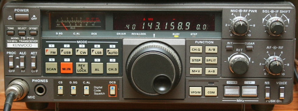
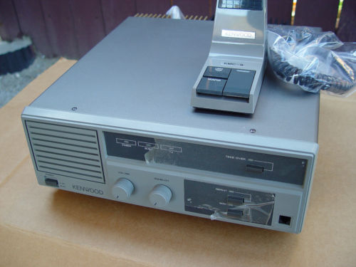
The Kenwood TS-711a is, more or less, the 2 meter twin
of my TS-440. The features are similar, and the styling is identical. Both
units were introduced at about the same time, and even use some of the
same accessories (such as the computer interface). This makes it a classic knob
and dial turner, and button pusher. Unlike the HF model,
the 2 meter version has a built in power supply, and can be plugged directly
into the wall. This is an all mode transceiver, and is not limited to FM
like most 2 meter units. There was also a third member of the family: the
TS-811, a 70 CM unit. This was Kenwood's middle range series.
The unit puts out 25 watts. This is enough power
for local communications, within the limitations of the 2 meter band. It
is also enough power to run a good quality linear amplifier up to full
rated power. I plan, in the near future, on getting a linear amp for this
unit. Mirage makes a suitable unit, which puts out 160 watts, and is capable
of multi-mode (including FM) operation. This should give me a respectable
amount of power, for local operation, and still be within the capability
of the 42 amp power supply which runs my shack. The Mirage has a claimed
current draw of about 20 amps, which still leaves plenty in case I wish
to operate the linear and my TS-440 HF at the same time. It is unlikely
that I will ever wish to do this, but it is comforting to know that the
capability is there if I need it. Output is continuously adjustable, via the RF
PWR knob, from 2 watts, up to the maximum of 25.
 Hitting any of the mode buttons to change mode generates a Morse code beep
announcing the new mode selected. The main reason I selected this unit for my
shack, is that it is capable of all mode operation. The majority of 2 meter units
out there are FM only. I don't know how much SSB or CW I will be using on two
meter, but it's good to have the option. Frequency can be set in increments as
small as 5 KHz.
Hitting any of the mode buttons to change mode generates a Morse code beep
announcing the new mode selected. The main reason I selected this unit for my
shack, is that it is capable of all mode operation. The majority of 2 meter units
out there are FM only. I don't know how much SSB or CW I will be using on two
meter, but it's good to have the option. Frequency can be set in increments as
small as 5 KHz.
This unit has the optional speech chip, which was thought to be a very big deal back in the 80's, when digital technology was novel and just coming of age. Today, it seems kind of silly and quant. The speech chip announces, in a pleasant female voice, any frequency changes or mode changes that I make - 80's high tech. The unit also has the tone board, which was an option back in the eighties, but is certainly a requirement these days. This is also one of the earlier units to be capable of computer control. An optional adapter board must be added, along with a level converter for RS-232C.
There are 40 memory locations available in this unit. Each can store frequency, shift, and tone. The last three can store two separate frequencies to be worked as a split. This is a nice feature which somewhat compensates for the 600KHz non adjustable offset of the 711. With the tone card installed, the unit is capable of selecting between 37 tones from 67 to 250.3 Hz.
The transceiver is capable of shifting the receive frequency up to 9.99 KHz, using the RIT control. It is also capable of shifting the receiver passband, through use of the IF shift control. The unit also has scanning features, due to an early version of computer control, and an eighties era microprocessor. Scanning can be done of segments of the band, or of the memory locations. You can also set a particular memory location for an alert, anytime it shows activity. A DCS feature allows the radio to respond to tone alerts or calls.
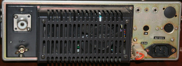
Though this is of the same series as the TS-440,
and shares that unit's all mode operation, the TS-711a is a bit less capable.
In particular, it is missing many of the connections, which give the HF
unit so much of it's flexibility. The rear panel features an antenna connector,
ground, power connectors for 120v and 13.8 volt, computer interface, and
audio jacks. Most activity, on the two meter band, is FM, making it hard
for many ham operators to justify the expense of an all mode radio.
To properly use the radio to its full potential, it should be hooked up to a
vertical antenna for FM, and a horizontal dipole for SSB.
The two meter band is, by far, the most popular ham band in the world. This is largely a local band, though very occasional skip and DX may be worked. The two meter band is 4 MHz wide, going from 144MHz to 148MHz. Though the band is not channelized, the heavy use of repeaters on the band means that there will generally be a number of repeater "channels" which will vary according to location. Repeater use is in FM mode, and requires an offset, which is usually +/- 600 KHz. More on this below.
The maximum normal range usually given for two meter is 190 miles, which would be a surprise to most ham radio operators. I regularly hit other radios at 20 - 40 miles, and can sometimes hit repeaters at longer distances, but radio to radio communications at 190 miles on two meters is a real matter of luck, unless you are in a high flying plane, or possibly orbiting the Earth. As a VHF band, two meter has a range based upon line of sight, which is a function of antenna height. Line of sight can be pretty easily calculated.
Multiplying the height of the antenna (in feet) by two, and then taking the square root will give the line of sight of a given transceiver. Doing this for both transceivers and then adding the answers will give you the line of sight. As an easy example, if your antennas are eight feet high, multiplying this by two will give sixteen. The square root of sixteen is four. If both antennas are at eight feet, then adding the results together would give a range of 8 miles. In practice, due to atmosphere effects, you can multiply this by about 15%.
Like all amateur services, two meter has a
band plan.
These are voluntary plans, and technically are not legally binding; but as
ham operators are required to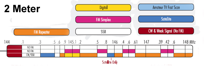 adhere to standard operating practices, and not
cause interference with other operators, a number of precedents have been set,
in which the FCC enforces a local or national band plan.
adhere to standard operating practices, and not
cause interference with other operators, a number of precedents have been set,
in which the FCC enforces a local or national band plan.
As can be seen from the band plan, FM repeater use predominates. This has become so popular that the vast majority of two meter radios sold, do not have the capability to operate in any other mode. Most radios used on the band are handhelds or mobiles, with just a very few base units out there. There is a small portion of the band dedicated to CW (Morse code) and weak signal; but this seems little more than a carry over from the days when novices were limited to CW on VHF. There are a very few sections dedicated to SSB, for those who try to work scatter or do DX on VHF. For some, this is a challenge and a goad, since DX on VHF is difficult. There are also a couple of small sections dedicated to Satellite.
Some small portions of the band are dedicated to FM simplex. This can be a convenient way to carry on private conversations, free from the crowding that often occurs on repeaters. Contacts can be made on repeaters or calling channels and then moved to the simplex frequencies. This also gives a certain measure of privacy. At the old spacing of 25khz, there is the potential for 66 separate users on the segments of the band reserved for simplex. With the new 12.5 KHz spacing coming into play, there is room for twice that number. If the entire band were channelized at the old spacing, there would be 160 channels.
With all of the space, and the relatively short range of 2 meter, the band is not what I consider to be crowded. In my local area, only one of the repeaters is regularly busy, and even this one is very slow late at night. Working simplex is a bit more fun, and allows for a fair degree of privacy. Simplex is rather short ranged, being limited to line of site on your particular radio. In a mobile unit, it could mean 5 to 8 miles, or perhaps ten to fifteen if talking to a base. For a handheld, it is probably a mile or two
Wow! Is there ever an abundance of material on how to make a two meter antenna. This is an extremely popular band, and antenna matters are very interesting to most radio amateurs. Due to space limitations, I was unable to do anything very elaborate. I had considered several ideas, but finally went the very conventional route. I made myself a horizontal dipole for AM and SSB, and a modified version of a J-pole, called a Slim Jim for FM. The dipole is essentially three feet of wire, and the Slim Jim is about triple the amount of copper tubing - simple.
One great thing about my two meter station is that it is single band - one band,
one antenna. This means matching the antenna once, and then leaving it be.
There are no recurring worries about SWR, tuning, or cable loss. Yes, VHF losses are greater
in coax than those at HF frequencies, but this is all related to SWR, and SWR
can be kept very low in a single band system. I do prefer to swap between the
horizontal and the vertical, when I change operating modes, but this is a minor
inconvenience. Lately, when I wish to operate in FM mode, I use my
Azden 6000,
rather than my Kenwood.
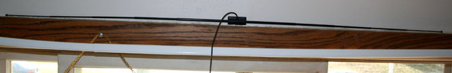
My first antenna was a
cheap little dipole made from a pair of telescoping radio aerials. Technically,
I suppose this is a horizontal dipole, made from telescoping antenna sections;
but there was no balun, and the very thin coax cable is permanently attached. In
addition, I did not know any better than to have the antenna mounted over my
window and only a couple of inches above a parallel metal curtain rod, which
certainly coupled with the antenna. I also had a part of the
 coax run right
alongside the antenna elements and parallel to them - every possible thing was
done wrong. I am amazed
that it worked and even more amazed that it did not fry my finals. Thank
goodness for the protection circuits in the TS-711 radio. I did notice that from
time to time, the transmitter section of the radio would seem to go out of
service. Letting it sit for a few moments would usually fix this. In addition,
turning the RF all the way down to the lowest setting, of two watts, would
usually prevent this from occurring at all. Ignorance is
bliss, and God protects fools and drunkards - well maybe.
coax run right
alongside the antenna elements and parallel to them - every possible thing was
done wrong. I am amazed
that it worked and even more amazed that it did not fry my finals. Thank
goodness for the protection circuits in the TS-711 radio. I did notice that from
time to time, the transmitter section of the radio would seem to go out of
service. Letting it sit for a few moments would usually fix this. In addition,
turning the RF all the way down to the lowest setting, of two watts, would
usually prevent this from occurring at all. Ignorance is
bliss, and God protects fools and drunkards - well maybe.
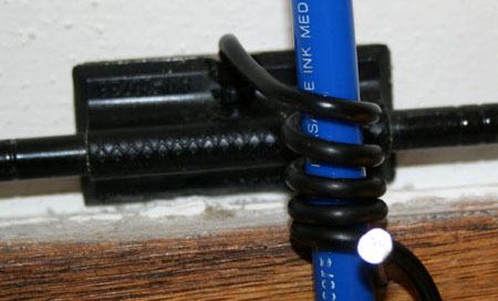
Once I got an idea of what I was doing, I improved the antenna slightly, by winding four turns of the coax around a piece of tubing (a pen actually), to make a choke. I also removed the curtain rod, and rerouted the coax to be perpendicular to the radiating elements. The antenna works much better now, and is still used for occasional attempts on SSB. I had considered making a standard dipole, with balun; but for now, this little antenna is good enough for the occasional use to which it is put.
My second antenna was
a magnet mount 2 meter unit, stuck to a large piece of sheet metal. The antenna,
and its sheet metal base sat on the table in my library. It actually
worked acceptably well, far better than the little dipole (probably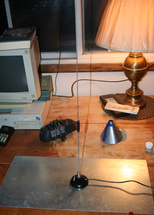 because of the vertical polarization, which is the same as that on most mobiles
and repeaters) and I could hit most of the local repeaters. A number of radio
operators do such things. Though it worked well enough, it was unsightly, and
took up lots of room, that could have been used for other things. The table upon
which the antenna was set up is my work table. With the antenna taking half of
it up, mush of my projects spilled over to my desk. This antenna is now on my
car, and mostly used by my Azden, which is my usual mobile radio.
because of the vertical polarization, which is the same as that on most mobiles
and repeaters) and I could hit most of the local repeaters. A number of radio
operators do such things. Though it worked well enough, it was unsightly, and
took up lots of room, that could have been used for other things. The table upon
which the antenna was set up is my work table. With the antenna taking half of
it up, mush of my projects spilled over to my desk. This antenna is now on my
car, and mostly used by my Azden, which is my usual mobile radio.
I have heard stories of magnet mount antennas being stuck to the top of refrigerators, metal utility shelves, and even bits of ducting or screening. As long as the square footage, can make a decent ground plane, and provide a good ground reflection, it is amazing what you can do. The sheet metal base sits in my basement until I find some use for it, probably as a ground plane for some home brew antenna of the future.
My current antenna is a homebrew modification of the classic J-pole called a Slim Jim. It is presently mounted on the wall of my shack, but will eventually be going up in my attic. The extra five or ten feet of height could get me a few more miles of range. IN VHF/UHF, height is critical to range. For more information on this great antenna design, and how it was made,
I have set up an antenna page about it here.
I heartily recommend this antenna, and it will probably be my last two meter antenna. It was easy to build, easy to tune (despite rumors that such antennas are not), and very inexpensive. Many make such antennas out of wire, or even out of feedline. I chose to use soft copper tubing, as it is easy to work and required no cutting or welding. The antenna sits on my wall, hanging by a bit of pull string. I have been very careful to mount it at least 20" away from any metal.
Though a good radio is important, there is little argument that the antenna is the most important part of a radio system. Since I have improved my little dipole, and particularly since I have put together my new Slim Jim, my friends on the air have made a number of comments asking if I have a linear, or have some sort of new radio. As much as the importance of the antenna is widely known and accepted, we are all still just a little surprised at how much difference these bent and folded lengths of wire and pieces of tubing can make.
| Modes | LSB (A3J), USB (A3J), CW (A1), AM (A3), FM (F3), FSK (F1) | ||
| Antenna Impedance | 50 Ohms | ||
| Grounding | Negative | ||
| Power Requirements | 120v / 13.8v | ||
| Current Drain | Receive Mode with no input | 1.2 amps | |
| Transmit Mode | 6.5 amps | ||
| Operating temperature | -10 to +50 C (+14 to +122 F) | ||
| Dimensions | Wide
High Deep |
10.6 Inches
3.78 Inches 10.2 Inches |
|
| Weight | 15.6 Pounds | ||
|
|
|||
| Frequency range | 144mhz-146mhz | ||
| Input Power | LSB, USB, CW, FM, FSK | 25 watts | |
| AM | 25 watts | ||
| Modulation | LSB, USB | Balanced Modulation | |
| FM | Reactance Modulation | ||
| AM | Low Level Modulation | ||
| Spurious radiation (CW) | Less Than -60 db | ||
| Carrier Suppression | More Than 40 db (With 1.5 KHZ Reference) | ||
| Unwanted Sideband Suppression | More Than 40 db (With 1.5 KHZ Reference) | ||
| Third Order Distortion | More than 26 db below one of two tones | ||
| Maximum Frequency Deviation (FM) | 5 KHZ | ||
| Frequency Response (-6 db) | 400 to 2600 HZ | ||
| Microphone Impedance | 500 to 600 Ohms | ||
|
|
|||
| Circuitry | Double Conversion Superheterodyne | ||
| Frequency range | 144mhz-146mhz | ||
| Intermediate Frequency | 1st: 30.265 MHZ, 2nd: 10.695 MHZ, FM: 455 KHZ | ||
| Sensitivity | LSB, USB, CW, FSK
(At 10 db S/N) |
less than .13uV | |
| AM (At 10 db S/N) | less than .13uV | ||
| FM (At 12 db SINAD) | Less Than 0.2 uV | ||
| Selectivity | LSB, USB, CW, FSK | -6 db | 2.2 KHZ |
| -60db | 4.8 KHZ | ||
| AM | -6 db | 2.2 KHZ | |
| -60 db | 4.8 KHZ | ||
| FM | -6 db | 12 KHZ | |
| -60 db | 24 KHZ | ||
| Squelch Sensitivity | LSB, USB, CW, FSK | 100 to 150 KHZ | Less Than 20 uV |
| FM | 1.6 to 30 MHZ | Less Than .32 uV | |
| Output | 2 Watts at 8 Ohms (5% Distortion) | ||
| Output Load Impedance | 4 to 16 Ohms | ||
| Frequency Accuracy | Less than .00001 error | ||
| Frequency Stability | Less than .00001 error | ||
Extended Transmit Frequencies:
- Remove the top cover and locate the control unit (X53-1410-XX)
- Cut diode D30, xmit now 141.000 TO 150.995 MHz.
The problem with doing this mod is that there is no one you can legally talk to un the extended frequencies, you risk fine or loss of license, and there is the possibility of doing the mod wrong and damaging your radio. You don't even want to think about what will happen, if these frequencies are in use by local police or fire. The nearest civilian frequency is the MURS band, which starts at 151.82 MHz.
Power tweak:
There are two other mods of which I am aware. I recommend neither. One is to tweak the final, so that 35 watts is put out, instead of 25 watts. This will certainly shorten the life of your radio, and may blow the final one day. It is also pointless. Such a mod would add perhaps 1 db to output - not even noticeable. The final output transistor is a Mitsubishi M57727. A number of misled radio hackers have noted that this transistor is rated at 37 watts. Though power can be increased from 25 watts to 35 watts, while staying within the specs of the component, this allows for no reserve capacity, will wear the chip faster and will produce more heat. The unit also becomes more sensitive to less than ideal SWR when operating at higher power.
The other mod permits doubling of the data transmit speed to 96K. It is a very involved mod, and I have yet to perform it.
Updates
are
coming
Once the IF-10A is installed, the radio may be connected through a special cable to the Kenwood IF-232C adapter, and from there to a standard com port. The connector from the IF-232C is a D25 type. At one time, most computers had a pair of com ports, one having a D25, and the other having a D9. These days a D25 to D9 cable will be required; but these are pretty common. IF-10A boards can still be found, but they are long out of production, and a certain amount of searching is required. A similar fate has befallen the IF-232C adapter. For the purist, this is grim news. Still, all is not lost. Aftermarket companies have filled the vacuum.
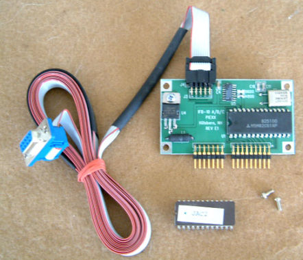
PIEXX offers a snap in replacement for the old IF-10A, that not only does the job of the original, but eliminates the need for an IF-232C. This is the route I took for this radio. This kit includes the required ROM chip, and installs in the same manner as the Kenwood factory unit, except for the method of cabling to the computer.
Where the Kenwood factory unit requires the IF-232c outboard box, and a pair of cables, the Piexx unit is able to directly connect to the computer RS-232C port. It does this via a 5' ribbon cable with a D9 connector, connected directly to the card. This connection lacks the elegance of the original six connector jack of the IF-10A; but this is more than made up for by the comparative ease of installation. The interface costs just shy of $100. Even so, when compared to the cost of an IS-232c, an IF-10a, and the required cables, it is a bargain. Even so, this is only half of the complete solution.
A signal interface completes the package, and allows the radio to do FSK, fax, and make use of various other digital modes, both to encode and decode. It can even get you SSTV. This is accessed through the ACC2 connector at the back of the radio. This is a thirteen pin connector. A mating plug is included with the radio, and is also widely available. With this plug, a signal interface can easily be made which will connect through a computer sound card. Such an arrangement would also permit logging and even recording of messages.
Many sound cards have multiple inputs (usually a line in, and a microphone), which allow for connection to more than one radio at a time, though signal levels may need to be adjusted. For connection to more than two radios, you will need to install a special sound card with multiple inputs. These are designed for home recording studios, and are a bit more costly than normal sound cards, though you are still only talking $100 - $150 for a nice sound card (better than the one you already have) that will permit connection of up to four radios. If you want to keep your current sound card, an add on card with an extra pair of inputs and outputs can usually be found for $50 - $100. Cards with breakout boxes can have input/output connectors for up to eight radios.
Once the cards and connections are in place, you will need software. There are a number of packages in place for computer control of your radio, and countless programs for packet, FSK, and various digital modes. Once you are connected, a whole new world opens up. I am putting together a page about the various bits fo software, the digital modes available, how to use them and what they sound like over the air. For now I recommend simply doing a search on radio digital modes, and on ham radio software.
Repeaters
A repeater is a radio, typically FM, that receives on one frequency and retransmits on another. This is done so that large powerful stations may be set up at good locations, to extend the range of smaller more portable stations. For many ham operators, and most newcomers, this is the heart of two meter radio. I have added this section because when I first got started in ham, I had no clue about how to use a repeater, and could find little information for beginners. It is assumed that everyone knows how to use one. Surprisingly, repeater use is a fairly new development. It is amazing to some of the old timers, just how much the face of two meter has changed, mostly due to repeater development. It is amazing to some newcomers that two meter could ever have existed without repeaters. With the exception of a rare experimental station, repeaters on two meter were almost unheard of before the seventies. Even then, they were by no means common. Most communication was simplex, using beam antennas, much like HF today.
Amateur repeater use was an outgrowth of the smaller, cheaper technology being developed for commercial and PS radios. Police, fire, and government, as well as some commercial users, had been using repeaters for years. When the technology filtered down to Amateur users, it began with use of surplus or cast off commercial and PS gear. Eventually, by the late seventies, and early eighties, most two meter radios could work splits, and even use tones. Previously working split frequencies required the use fo an external VFO. Early repeaters simply retransmitted anything powerful enough to pass the squelch of their receiver. This caused much retransmission of static and RF noise. Eventually special tones were required to break through the squelch settings. They came in two flavors - tone burst, and CTCSS.
Tone burst worked by generating a tone which would open the squelch on a repeater so that a transmission could be made. The tone would be transmitted for a brief period of a half second to a second or so. The repeater would open, and stay open as long as a carrier was sensed. To a certain extent, this was a means to limit use to authorized users, but was mostly meant to cut down on power usage, and wear. It helped to insure that the repeater was only transmitting when a user was present. This was also a way to prevent congestion of the airwaves, by preventing the reception and retransmission of static. The problem with tone burst was that it sometimes mistook static for a carrier, and the repeater would remain open. The roger beep that many CB user have on their radios was originally an attempt to sound like a professional user with a tone burst. I am unaware of any current tone burst use. It has been replaced by CTCSS.
Motorola came up with their PL (Private Line) system of subaudable CTCSS (Continuous Tone Coded Squelch System) tones. This quickly took over from the old tone burst system, and made repeater use more secure, as well as more convenient. It was a great improvement. As the name implies, this system will inject a tone into the carrier for the entire time of the transmission. As soon as the transmission ceased, the tone stops and the repeater closes. The tones are not really subaudable, but are very quiet and unobtrusive. I regularly hear the 127.3 tone on my local repeater as a low hum. Most repeaters have filters for these tones, and they are filtered out of retransmissions.
 Anybody can put up a repeater. There are no
special fees or licensing required. This was not always true. In 1973, the FCC
put in place some pretty heavy requirements including site surveys, and impact
statements. These requirements were eventually relaxed and then dispensed with.
You will still need to get a hold of your local repeater coordinator, just to
make certain that you will not be causing any difficulties for existing users;
but it's always easier to work with people than with government agencies.
Anybody can put up a repeater. There are no
special fees or licensing required. This was not always true. In 1973, the FCC
put in place some pretty heavy requirements including site surveys, and impact
statements. These requirements were eventually relaxed and then dispensed with.
You will still need to get a hold of your local repeater coordinator, just to
make certain that you will not be causing any difficulties for existing users;
but it's always easier to work with people than with government agencies. A number of amateurs create homemade repeaters by linking a pair of radios together at different frequencies, with one being the receiver and the other being the transmitter. This can be done for a couple hundred dollars or even less. There are even some small multi band handheld or mobile radios that are capable of cross band repeating - receiving on one band and then retransmitting on another.
Repeater use has become so common and popular that you can now buy ready made small repeaters from many radio manufacturers. The photo to the right shows a small repeater made by Kenwood. This unit is typical, and puts out fifty watts. Such a unit is programmable for a single channel pair at a time, and is set up for a pair of antennas, and would also have a tone squelch (For CTCSS). A single antenna can be used through installation of a duplexer. Such a unit would cost $1500 - $2000 new, or perhaps a third of this used.
Typically clubs and other organizations that put up repeaters would use a rack mount system of considerably more power and sophistication. This will usually put out hundreds of watts, and have antennas mounted on high buildings, or on leased spaces of commercial radio towers. Such a system represents a considerable amount of time, money, and effort. Most repeaters are open to the public, and listed in repeater directories, so that they can be accessed by anyone who wishes. If you use a repeater regularly, it is considered proper to either join the sponsoring organization, or perhaps make a donation from time to time, towards expenses.
Using a repeater is simple. An online listing fo repeaters can be found by following this link, and selecting your local area. Repeaters are identified by their transmit frequency, thus the 146.910 repeater transmits on 146.910. The receive frequency is designated by the split. A 600 KHz split is universal, and is the default split programmed into all modern radios in the Untied States. The split can either be 600 KHz above or below the repeater transmit frequency. In addition to splits, repeaters typically use one of a number of CTCSS tones. A typical repeater listing in a directory will look like this:
146.910 127.3 -
What this is telling you is to set your radio to receive on 146.910, set a tone of 127.3 hz, and set a negative split. The split size (600 KHz) should already be programmed into your radio, so all you will have to designate is if it is positive or negative. With a number of repeaters programmed into your radio, you will have an easy link to all the hot spots in your local area. The table below shows the repeaters I have set in my TS-711A.
This will be of no use to anyone not living in my local area (Metro Milwaukee). It is the list of my local repeaters.
| Repeater | Transmit (user receive) | Receive (user transmit) | Tone | Offset | Location |
| MRC | 146.910 | 146.310 | 127.3 | 600Khz - | Milwaukee |
| MAARS | 145.130 | 144.530 | 127.3 | 600Khz - | Milwaukee |
| WARC | 147.390 | 147.990 | 127.3 | 600Khz + | Pewaukee |
| SEWFARS | 146.820 | 146.220 | 127.3 | 600Khz - | Wales |
| MRAC | 145.390 | 144.790 | 127.3 | 600Khz - | Milwaukee |
| ORC | 146.97 | 146.37 | 127.3 | 600Khz - | Cedarburg |
| MSOE | 145.270 | 144.670 | 127.3 | 600Khz - | Milwaukee |
| Mcares | 147.165 | 147.765 | 127.3 | 600Khz + | Milwaukee |
| Ozares | 147.33 | 147.93 | 127.3 | 600Khz + | Port Wash |
| group | 147.21 | 147.81 | 127.3 | 600Khz + | Slinger |
| Manual | Eham Review | Repeater list | |